


15
RDV4136 Series Direct Vent Gas Fireplace
10010618
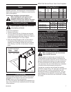
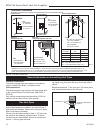
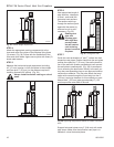
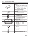
7.5'
(2.3m)
A
B
A + B = 17' (5.2m) Max.
1 x 90° elbow in horizontal plane = 3’ (914mm)
FP1238
Fig. 19 Maximum vent run with elbows.
• For each 45° elbow installed in the horizontal run,
the length of the horizontal run MUST be reduced by
18” (457 mm). This does not apply if the 45° elbows
are installed on the vertical part of the vent system.
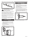
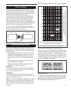
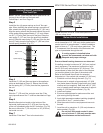
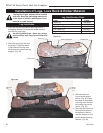
• The maximum number of elbow degrees in a system
is 270°. (Fig. 20)
Vertical Sidewall Installation
Twist Lock Pipe
STEP 1
Locate vent opening on the wall. It may be necessary
to first position the fireplace and measure to obtain hole
location. Depending on whether the wall is combustible
or noncombustible, cut opening to size. (Fig. 21)
For combustible walls first frame in opening.
Example:
Elbow 1 = 90°
Elbow 2 = 45°
Elbow 3 = 45°
Elbow 4 = 90°
Total angular variation = 270°
1 + 2 + 3 + 4 = 270°
FP1239
Fig. 20 Maximum number of elbow degrees.
1
2
3
4
NOTE: When using flex vent, the opening will have to
be measured according to the 1/2” (13 mm) rise in 12”
(305 mm) vent run.
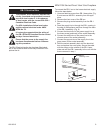
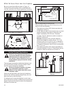
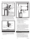
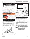
Combustible Walls:
(Fig. 21) Cut a 9³⁄₈”H x 9³⁄₈”W (240
x 240 mm) hole through the exterior wall and frame as
shown.
Noncombustible Walls:
(Fig. 21) Hole opening must
be 7¹⁄₂” (190 mm) in diameter.
VO584-100
Vent Opening
2/99 djt
Vent Opening for Combustible Wall
9³⁄₈”
(240mm)
9³⁄₈”
(240mm)
Fireplace Hearth
Framing
Detail
Opening for Noncombustible Wall
7¹⁄₂”
(190mm)
VO584-100
Fig. 21 Locate vent opening on wall.
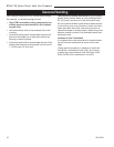
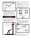
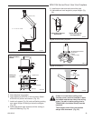
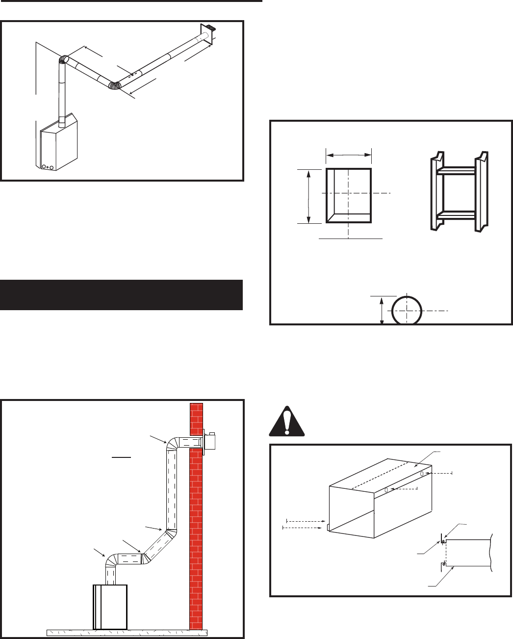
STEP 2
Measure wall thickness and cut zero clearance sleeve
parts to proper length (MAXIMUM 12”/305 mm). Assem-
ble sleeve and attach to firestop with #8 sheet metal
screws (supplied). Install firestop assembly. (Fig. 22)
Zero clearance sleeve is only required for
combustible walls.
ZCS101
Zero Clearance Sleeve
3/11/99 djt
Max. Length
12” (305mm)
#8 Screws (2)
#8 Screws
(2)
Adjustable
Zero Clearance
Sleeve
#8 Screws
(2)
Adjustable Zero Clearance Sleeve
ZCS101
Fig. 22 Adjustable zero clearance sleeve.
Firestop
STEP 3
Place fireplace into position. (Fig. 23) Measure the verti-
cal height (X) required from the base of the flue collars
to the center of the wall opening.