


37
RDV4136 Series Direct Vent Gas Fireplace
10010618
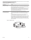
Optional Accessories
FP1004
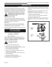
Fan placement
DV360/580 Series
1/25/00 djt
Cold Air Box
Side View
Front of
Unit
Hearth Pan
Base Pan
FK12 Fan
FP1004
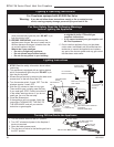
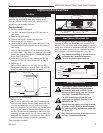
Fig. 57 FK12 Fan Kit placement.
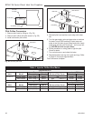
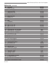
Black
White
Ground
FP394
WIRING DIAGRAM
11/20/96
Fan
Temperature
Sensor
Speed
Control
FP1025
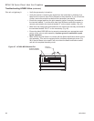
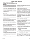
Fig. 59 FK24 fan wiring.
Fan Kits
Installation of the fan kit is best completed prior to
installing the fireplace. If done after the fireplace is
installed, all lava rocks must be fully removed so the
burner tray can be easily lifted out.
Fan Assembly
1. Remove valve access panel.
2. Turn OFF the electricity and turn OFF the manual
gas valve.
3. Remove the glass door.
4. Remove the log set, embers and lava rock.
5. Remove the rear log support.
6. Remove the 10 sheet metal screws and two (2) 1/4-
20 bolts that secure the burner tray to the combus-
tion casing.
7. Remove the burner tray from the fireplace by first tilt
-
ing up the back. Take care not to damage the formed
burner tray gasket. If the gasket is damaged, replace
it with Part # 10010592.
8. While holding the burner tray, remove the flex gas
line from the shut-off valve (turned OFF in Step 2).
9. FK12: Fig. 57
Secure fan to cold air box and plug fan into EB-1.
Reassemble fireplace in reverse order. Use a 50/50
soap and water solution to check for leaks.
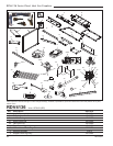
TP
TH
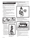
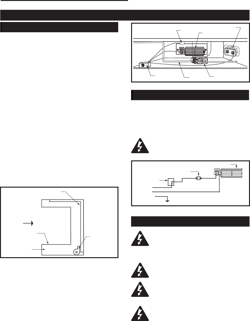
FP1811
FK24
fan placement
7/07 djt
Electrical Box
Heat Sensor
Fan
Fan Speed
Switch
Gas Line
Valve
FP1811
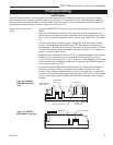
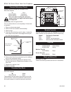
Fig. 58 FK24 fan placement.
The fireplace, when installed, must be
electrically connected and grounded in
accordance with local codes or, in the
absence of local codes, with the current
CSA C22.1 Canadian Electric Code.
For USA installations follow the local
codes and the national electrical code
ANSI/NFPA No. 70.
Should this fan require servicing or repair
the power supply must be disconnected.
For rewiring of any replacement parts refer
to Figure 59.
Any electrical re-wiring of this fan must be
done by a licensed electrician.
Wiring Instructions
Hard (direct) Wire Hook Up
First connect ground wire to ground stud located on
the base of either box. Black wire from supply should
connect to the variable speed switch. Alternate speed
switch wire connects to temperature sensor. Alternate
lead from sensor connects to fan. Alternate fan lead
connects back to the white supply wire. (Fig. 59)
Any electrical rewiring of this fan must be
completed by a qualified electrician.
Turn off all power before hook up.
FK24: Fig. 58
Secure fan to cold air box with two (2) washers and
nuts provided. Secure the fan speed switch with two
(2) nuts provided to the two (2) studs on the base
pan of the fireplace. Lay the burner tray upside down
in front of the fireplace. Secure the heat sensor over
the two (2) studs on the underside of the burner tray
assembly and secure with two (2) nuts provided. Re-
assemble the fireplace in reverse order. Use a 50/50
soap and water solution to check for gas leaks.
Fan installation complete.