


14
RDV4136 Series Direct Vent Gas Fireplace
10010618
FP1012
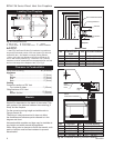
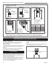
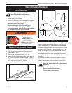
Top vent max run
1/25/00 djt
20' (6m)
7.5' (2.3m)
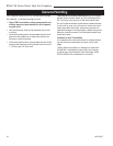
Pipe Straps
Every 3’ (914mm)
Firestop/Zero
Clearance Sleeve
Pipe
Straps Every
3’ (914mm)
FP1012
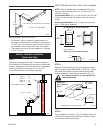
Fig. 17 Support straps for horizontal runs.
Since it is very important that the vent-
ing system maintain its balance between
the combustion air intake and the flue
gas exhaust, certain limitations as to vent
configurations apply and must be strictly
adhered to.
The vent graph showing the relationship between verti-
cal and horizontal side wall venting will help to deter-
mine the various dimensions allowable.
Minimum clearance between vent pipes
and combustible materials is one 1”
(25mm) on top, bottom and sides unless
otherwise noted.
When the vent termination exits through foundations
less than 20” (508 mm) below siding outcrop, the vent
pipe must flush up with the siding.
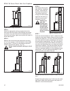
It is always best to locate the fireplace in such a way
that minimizes the number of offsets and horizontal vent
length of vent pipe from the flue collar of the fireplace to
the face of the outer wall.
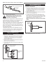
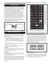
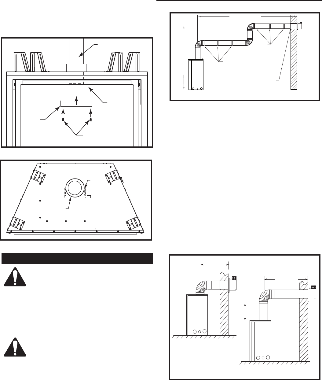
2'
(610 mm)
FP1821
horizontal plane
10/07
5' (1.5 m)
2'
(610 mm)
FP1821
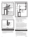
Fig. 18 Horizontal vent run.
Minimum Horizontal
Vent Run
Maximum Horizontal
Vent Run
Vertical Sidewall Applications
Horizontal plane means no vertical rise exists on this
portion of the vent assembly.
• The maximum number of 90° elbows per side wall
installations is three (3).
• If a 90° elbow is used in the horizontal vent run (level
height maintained) the maximum horizontal vent
length is reduced by 36” (914 mm). This does
not apply if the 90° elbows are used to increase or
redirect a vertical rise.
Example: According to the chart the maximum
vertical vent length in a system with a 7.5’ (2.3 m)
horizontal rise is 20’ (6 m) and if a 90° is required in
the horizontal vent it must be reduced to 17’ (5.2 m).
In Figure 19, Dimension A plus B must not be greater
than 17’ (5.2 m).
• The maximum number of 45° elbows permitted per
side wall installation is two (2). These elbows can be
installed in either the vertical or horizontal run.
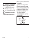
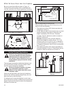
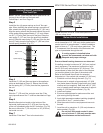
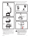
Be sure to install the baffle as shown in Figure 16.
Close half the opening when used on extended vent
runs. Be sure there is no lifting or ghosting of the flame.
Flue Pipe
Flue Box
Screws
Baffle
FP1863
Fig. 15 Install baffle to the deflector.
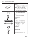
Baffle
Be sure this
portion is
towards the
front of the
fireplace
FP1864
Fig. 16 Baffle in position, top view.
Slot