


9
360DVS Series Direct Vent Fireplaces
10006326
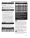
Top of unit to ceiling ................................. 36” (914 mm)
Front of unit to combustibles ................... 36” (914 mm)
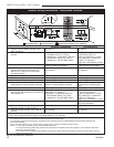
Appliance
Top .........................................0” (0 mm) to standoff
Bottom ..................................................... 0” (0 mm)
Vent End ....................... 1/2” (13 mm) to rear panel
Nonvent End (DVS2) .............................. 0” (0 mm)
Venting
Concentric sections of DV Vent:
Top, bottom & sides ..............................
1” (25 mm)
Nonconcentric sections of DV Vent:
Side and bottom .................................... 1” (25 mm)
Top ........................................................ 2” (51 mm)
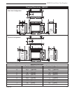
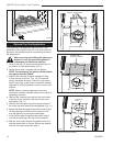
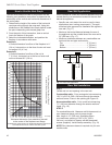
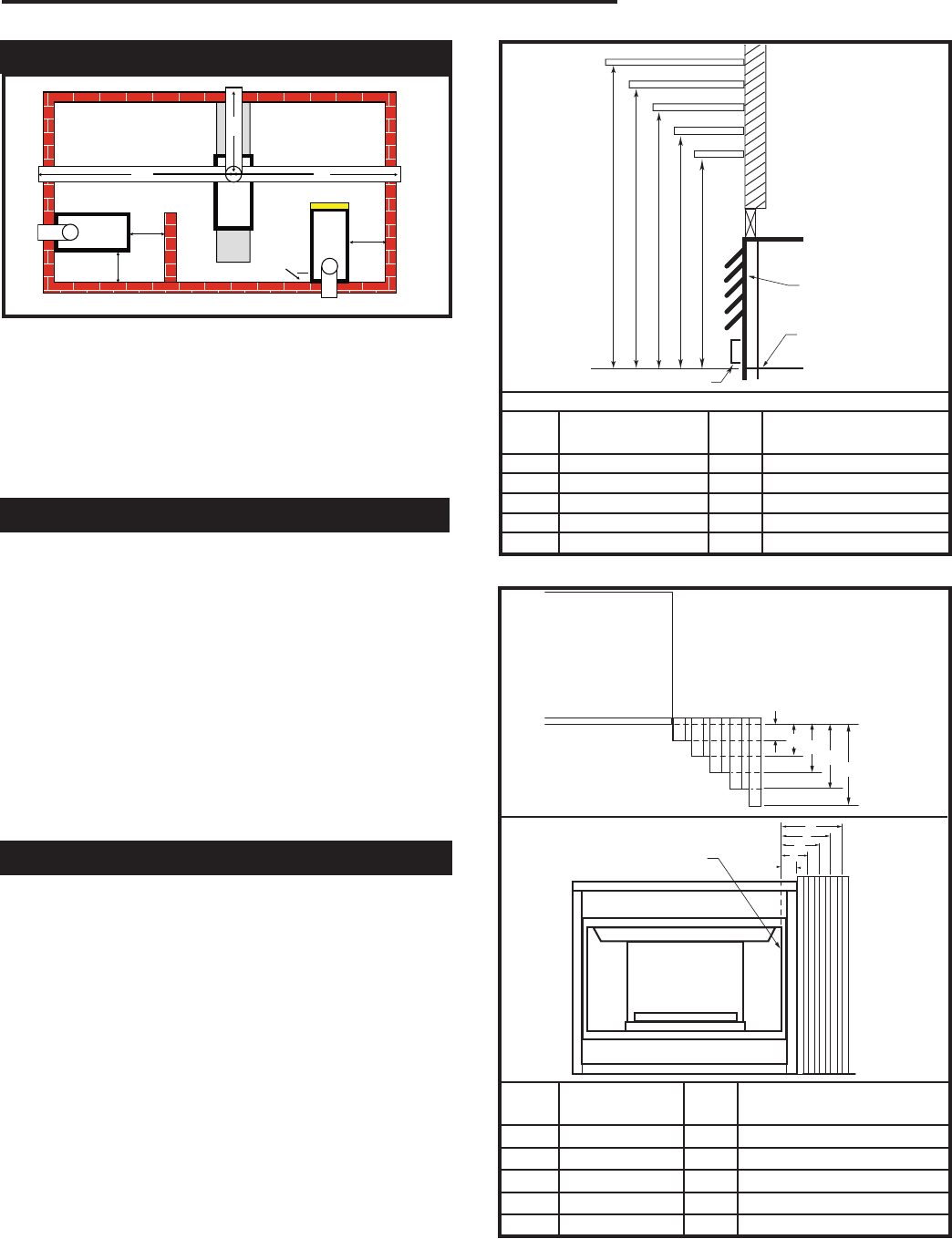
Mantels
The height at which a combustible mantel is fitted
above the fireplace is dependent on the depth of the
mantel. This also applies to the distance between the
mantel leg (if so fitted) and the fireplace. For correct
mounting height and width, refer to Fig. 4a and 4b and
the Mantel Chart below.
The fitting of a bay window trim kit does not affect the
distances and reference points referred to in the dia-
gram and chart.
Noncombustible mantels and legs may be installed at
any height and width around the appliance.
When using paint or lacquer to finish the mantel, such
paint or lacquer must be heat resistant to prevent dis-
coloration.
Clearance to Combustibles
A B C D E
V
W
X
Y
Z
CFM146
DV Mantel Chart
7/5/01 sta
Louvre Assembly
Top
Fireplace
Top of Combustion
Chamber
Bottom of Door Trim
Mantel Shelf Mantel from Top
Ref. or Breast Plate Ref. of Comb. Chamber
V 10” (254 mm) A 19” (483 mm)
W 8” (203 mm) B 17” (432 mm)
X 6” (152 mm) C 15” (381 mm)
Y 4” (102 mm) D 13” (330 mm)
Z 2” (51 mm) E 11” (297 mm)
Mantel Chart
CFM146
Fig. 4a Combustible mantel minimum installation.
CFM170
DV Builder Front
View
O
N
M
L
K
J
F
G
H
I
CFM197
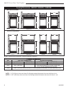
Mantel Corner Leg Chart
04/16/02 sta
Top View
Mantel Leg
CFM197
Front View
Side of Combustion
Chamber
Mantel
Leg
CFM170
Mantel Mantel Leg From Side
Ref. Leg Depth Ref. of Comb. Opening
F 10” (254 mm) K 11¹⁄₂” (292 mm)
G 8” (203 mm) L 9¹⁄₂” (241 mm)
H 6” (152 mm) M 7
¹⁄₂” (191 mm)
I 4” (102 mm) N 5
¹⁄₂” (140 mm)
J 2” (51 mm) O 3¹⁄₂” (89 mm)
Fig. 4b Combustible mantel leg minimum installation.
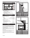
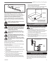
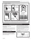
A Wall Location (Fig. 3)
Y (Minimum distance between a glass panel and a
parallel wall) = 3’ (914mm)
Z (Minimum distance between edge of a glass panel
and an adjacent wall) = 3” (76mm)
B Island Location (Fig. 3)
X (Maximum length of horizontal venting) = 20’ (6.1m)
Refer to the venting section in this manual for specific dimen-
sions.
Fig. 3 Locating your gas fireplace
Locating Your Fireplace
X
X
X
Y
Y
Y
Z
A
A
B
LU584-2
360DVS
locate fireplace
LU584-2