


17
360DVS Series Direct Vent Fireplaces
10006326
VO584-100
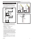
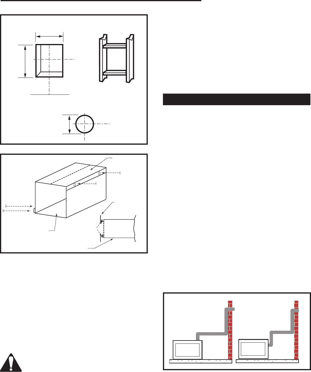
Vent Opening
2/99 djt
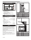
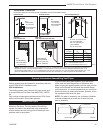
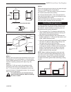
Vent Opening for Combustible Wall
9³⁄₈”
(240mm)
10³⁄₈”
(265mm)
Framing Detail
Vent Opening for Noncombustible Wall
7¹⁄₂”
(190mm)
VO584-100
Fig. 18 Locate vent opening on rear wall.
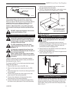
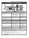
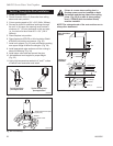
STEP 3
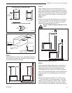
Measure the horizontal length requirement for the vent-
ing including a 2” (51 mm) overlap, i.e. from the elbow
to the outside wall face plus 2” (51 mm), or the distance
required if installing a second 90˚ elbow. (Fig. 20)
STEP 4
Install the 4” (102 mm) vent to the appliance collar
and secure with three (3) sheetmetal screws. Install
the 7” (178 mm) vent pipe to the appliance collar and
secure with three (3) sheetmetal screws. It is not neces-
sary to seal this connection.
It is critical there be no downward slope
away from the appliance when connecting
the vent or elbow.
STEP 5
Guide vent through the vent hole as you place the appli
-
ance in its installed position. Guide the 4”
(102 mm) and 7” (178 mm) collars of the vent termina-
tion into the outer ends of the venting.
Do not force the termination. If the vent pipes do not
align with the termination, remove and realign the vent-
ing at the appliance flue collars.
Attach the termination to the wall as outlined in the
instruction sheet supplied with the termination.
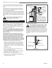
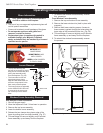
Vertical Sidewall Application
It is very important the venting system maintain its bal-
ance between the combustion air intake and the flue
gas exhaust, certain limitations concerning vent con-
figurations must be strictly adhered to.
• The vent graph (Fig. 16), showing relationship be-
tween vertical and horizontal side wall venting, will
help determine allowable dimensions.
• Minimum clearance between vent pipes and com-
bustible materials is 1” (25 mm) on top, bottom, and
sides, unless otherwise noted.
• When the vent termination exits through foundations
less than 20” (508 mm) below siding outcrop, the
vent pipe must flush up with the siding.
• It is best to locate the fireplace in such a way that
minimizes the number of offsets and horizontal vent
length. The horizontal vent run refers to the total
length of vent pipe from the flue collar of the fire-
place to the face of the outer wall.
NOTE: When installing the appliance as a rear vent
unit, the 90˚ transition elbow attached directly to the
rear of the unit is not included in the following criteria
and calculations. Unless it is specifically mentioned,
this elbow should be ignored when calculating venting
layouts.
FP1435
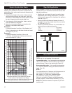
Fig. 20 Maximum three (3) 90° elbows per installation.
CFM135
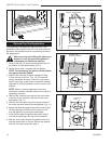
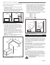
Zero Clearance Sleeve
2/26/01 sta
Maximum
Length
12” (305mm)
#8 Screws (2)
#8 Screws (2)
Firestop
Side View
CFM135a
Fig. 19 Adjustable zero clearance sleeve.
Zero Clearance
Sleeve
Zero Clearance
Sleeve