


16
360 DVS Series Direct Vent Fireplaces
10006326
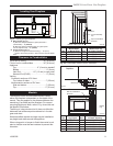
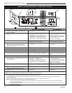
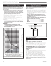
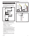
How to Use the Vent Graph
The vent chart should be read in conjunction with the
following vent installation instructions to determine the
relationship of the vertical and horizontal dimensions of
the vent system.
1. Determine the height of the center of the horizontal
vent pipe exiting through the outer wall. Using this
dimension on the Sidewall Vent Graph bellow, locate
the point intersecting with slanted graph line.
2. From the point of this intersection, draw a vertical
line to the bottom of the graph.
3. Select the indicated dimension, and position the
fireplace in accordance with same.
Example A:
If vertical dimension from floor of the fireplace is 11’
(3.4 m), horizontal run to the face of outer wall must
not exceed 14’ (4.3 m).
Example B:
If vertical dimension from floor of the unit is
7’ (2.14 m), horizontal run to the face of outer wall
must not exceed 8¹⁄₂’ (2.6 m).
3
4
5
6
7
8
9
10
11
12
13
14
15
16
17
18
19
20
21
22
23
24
25
26
27
28
29
30
3 4 5 6 7 8 9 10 11 12 13 14 15 16 17 18 19 20
eg: A
eg: B
DV Graph
rev. 8-8-02 rjs
Vertical dimension from floor of the unit
to center of the horizontal vent pipe
DV Graph
Horizontal dimension from outside of the wall
to the center of the fireplace vent flange
Sidewall vent graph showing the relationship between vertical and
horizontal dimensions for a Direct Vent flue system.
Fig. 16 Sidewall vent graph.
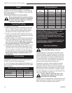
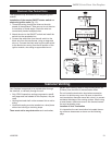
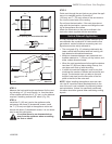
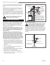
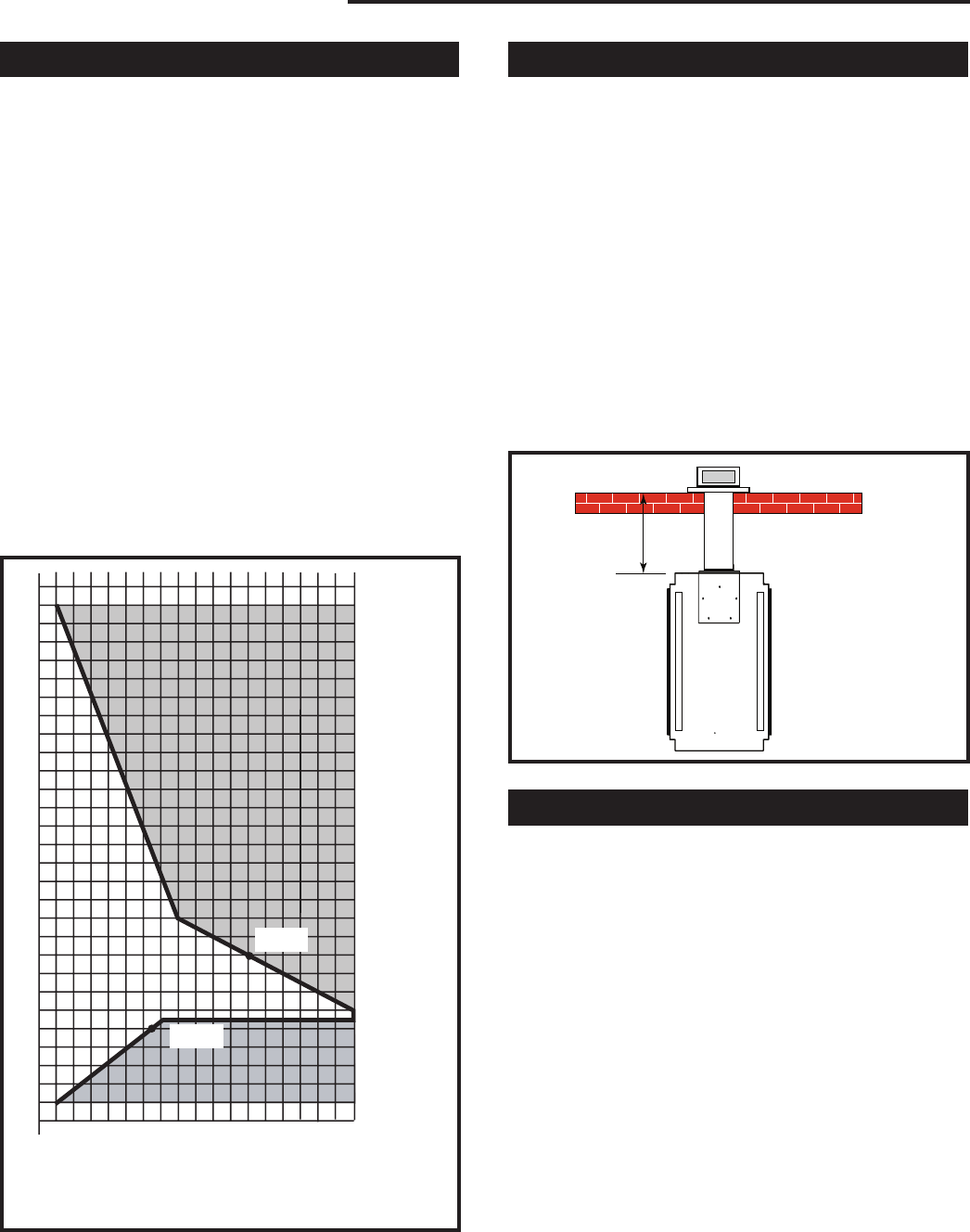
Rear Wall Application
When installed as a rear vent unit this appliance may be
vented directly to a termination located on the rear wall
behind the appliance.
• Specific rear vent starter kits must be used in these
applications (see ‘venting components’). The appli-
ance has been approved for installation flat against a
rear wall. (Fig. 17)
• Maximum horizontal distance between the rear of
the appliance and the outside face of the rear wall is
20” (508 mm). (Fig. 17)
• Minimum clearances between any combustible ma-
terial and the vent pipe sections are:
Top ..............................................2” (51 mm)
Sides ...........................................1” (25 mm)
Bottom .........................................1” (25 mm)
Max. 20”
(508mm)
FP1434
Fig. 17 Rear vent application.
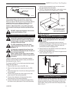
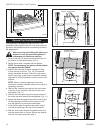
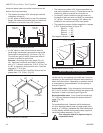
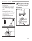
Rear Wall Installation
Step 1
Locate and cut vent opening in the rear wall.
Combustible walls: Cut a rectangular hole measuring
10³⁄₈” H x 9³⁄₈” W (265 x 240 mm) through the exterior
wall and frame. Frame in the opening per Figure 18.
Noncombustible walls: Cut a round hole measuring
7¹⁄₂” (190 mm) diameter through the exterior wall and
frame. (Fig. 18)
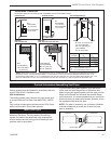
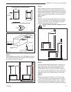
STEP 2
For combustible walls: Measure wall thickness and cut
zero clearance sleeve parts to proper length.
Max. length is 12” (305 mm). Assemble sleeve
to its maximum opening of 10³⁄₈” x 9³⁄₈” (265 x
240 mm), and attach to firestop with #8 sheetmetal
screws (supplied). Install firestop assembly. (Fig. 19)
NOTE: Zero clearance sleeve is required only for com-
bustible walls.