


19
360DVS Series Direct Vent Fireplaces
10006326
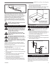
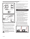
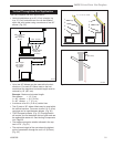
STEP 3
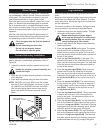
Place fireplace into position. (Fig. 26) Measure the verti-
cal height (X) required from the base of the flue collars
to the center of the wall opening.
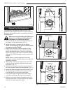
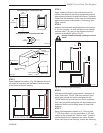
VO584-100
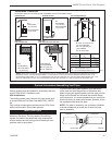
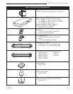
Vent Opening
2/99 djt
Vent Opening for Combustible Wall
9³⁄₈”
(240mm)
9³⁄₈”
(240mm)
Framing Detail
Vent Opening for Noncombustible Wall
7¹⁄₂”
(190mm)
VO584-100
Fig. 24 Locate vent opening on rear wall.
X
X
FP1439
Fig. 26 Vertical height requirement.
STEP 4
Apply a bead of silicone to the inner and outer flue
collars of the fireplace and using appropriate length of
pipe section(s) attach to fireplace with three (3) screws.
Follow with the installation of the inner and outer elbow,
again secure joints as described in “Connecting Vent
Pipes” section.
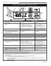
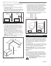
STEP 5
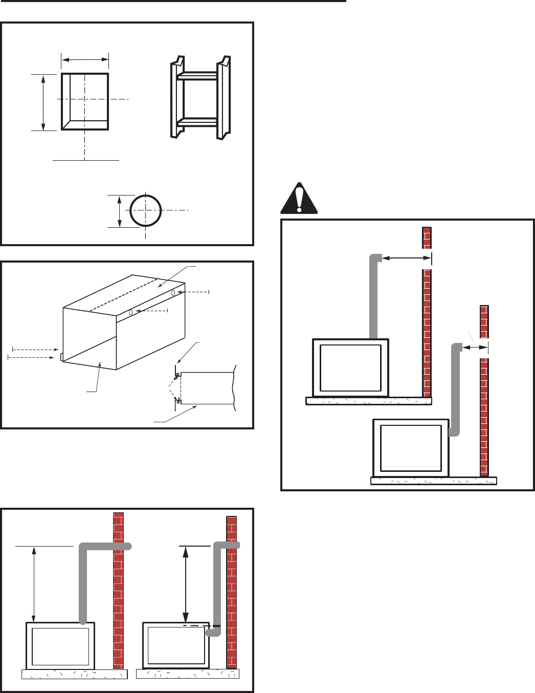
Measure the horizontal length requirement including a
2” (51 mm) overlap, i.e. from the elbow to the outside
wall face plus 2” (51 mm) (or the distance required if
installing a second 90° elbow. (Fig. 27)
Always install horizontal venting on a level
plane.
X
X
FP1441
Fig. 27 Horizontal length requirement.
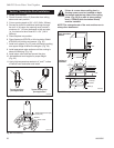
STEP 6
Use appropriate length of pipe section—telescopic or
fixed—and install. The 20” (508 mm) section of pipe
which goes through the wall is packaged with the
7DVSK starter kit, and can be cut to suit if necessary.
Seal vent pipe and firestop gaps with high temperature
sealant to restrict cold air being drawn in around the
fireplace.
STEP 7
Apply high temperature sealant to 4” (102 mm) and
7” (178 mm) collars, or to the termination 1” (25 mm)
away from the crimped end. Guide 4” and 7” collars of
vent terminations into respective vent pipes. Double
check vent pipes to see that they overlap the collars by
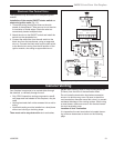
CFM135
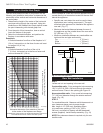
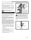
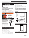
Zero Clearance Sleeve
2/26/01 sta
Maximum
Length
12” (305mm)
#8 Screws (2)
#8 Screws (2)
Firestop
Side View
CFM135a
Fig. 25 Adjustable zero clearance sleeve.
Zero Clearance
Sleeve
Zero Clearance
Sleeve