


40
360 DVS Series Direct Vent Fireplaces
10006326
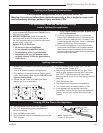
Wiring Instructions
The fireplace, when installed, must be elec
-
trically connected and grounded in accor-
dance with local codes, or in the absence
of local codes, with the current CSA C22.1
Canadian Electric Code. For USA installa-
tions, follow local codes and the National
Electrical Code
ANSI/ NFPA No. 70.
Any electrical rewiring of this fan must be
done by a licensed electrician.
Should this fan require servicing or repair,
the power supply must be disconnected. For
rewiring of any replacement parts, refer to
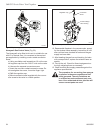
Figure 51.
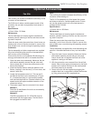
Method A (Not using EB-1; Fig. 52)
1. Connect the ground wire to the power supply line to
ground stud located on the base of the firebox.
2. Connect the black wire of the supply line to either
terminal of the speed control unit.
3. The second terminal of the speed control unit is
attached to either terminal of the thermal sensor.
4. The second terminal of the thermal sensor is con
-
nected to either terminal of the fan motor.
5. The second fan motor terminal is connected to the
white wire of the supply line.
C
B
A
Black
White
Ground
CFM105
FK-24 Wiring Diagram
9-29-00
A: Speed Control
B: Temperature Sensor
C: Fan
CFM105
Fig. 52 Method ‘A’ fan wiring diagram.
Remote Controls
Optional remote control units are available to control dif-
ferent functions of the appliance.
Model Function(s) Controlled
RC1 ON/OFF
RC2 ON/OFF & Temperature
IMTFK Wall-mounted thermostat control
Decorative Trim Frame Kit
The DV360TKMP Medium Trim Kit in polished brass is
available for the 360DVS2 model only.
Each kit contains 4 polished brass trim pieces and the
necessary attaching screws to frame one side window of
the unit.
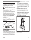
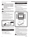
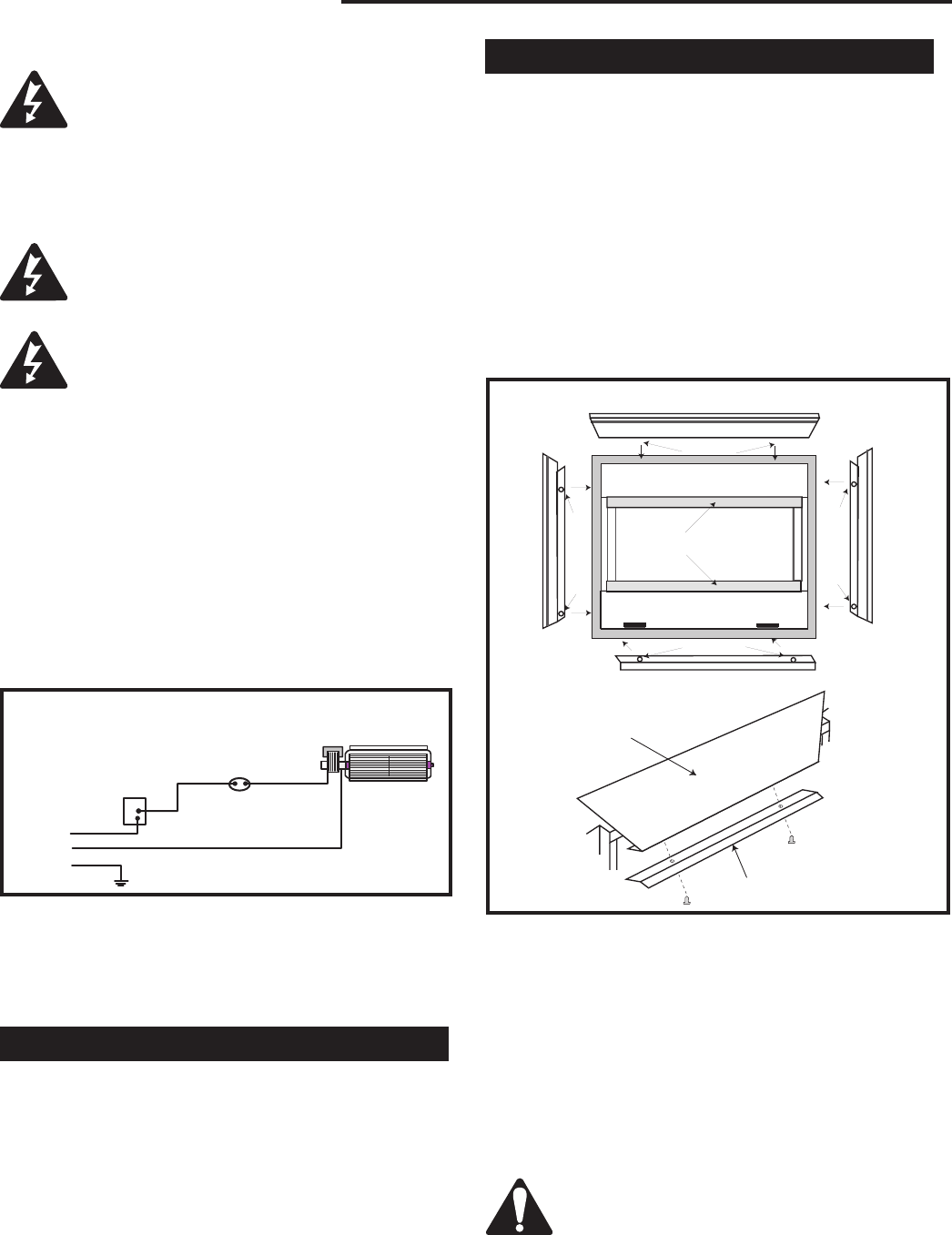
Installation (Refer to Fig. 53)
1. Remove the top louvre assembly.
2. Lower the bottom louvre assembly to expose the lou
-
vre hinges. Unscrew the retaining screws and remove
the louvre assembly from the hinges.
3. Remove the retaining screws that secure the top
deflector plate (above the top louvre opening), and
remove the plate.
4. Using the screws provided, attach the lower trim piece
to the predrilled holes in the lower edge of the bottom
louvre opening.
5. Using the screws provided, attach the two side trim
pieces to the predrilled holes in the vertical side frames.
6. Use the top deflector plate and the screws removed in
step 3 to clamp the top trim piece in place. With the trim
piece in place along the top edge, refit and secure the
top deflector plate.
7. Reattach the lower louvre panel to the hinges and re-
place the top louvre assembly.
All protective plastic wrap must be removed
from the trim pieces before the appliance is
put into service. If plastic wrap is not re-
moved, a health or fire hazard may develop.
Method B
For instruction on wiring the EB-1 Electrical Junction Box,
see section EB-1 Electrical Junction Box Connection on
Page 10.
Fig. 53 Decorative trim frame installation.
Trim - bottom
Trim - top
Trim Window Top/Bottom
S
c
r
e
w
s
S
c
r
e
w
s
Screws
Screws
Top trim piece
Top deflector plate
Trim-left
Trim-right
FP1449