


11
360DVS Series Direct Vent Fireplaces
10006326
FP297A
INSTA VENT FREE
UVHB26 GAS SUPPLY
7/1/98
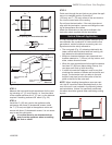
1/2” Gas Supply
1/2” NPT X 1/2” Flare Shut-Off Valve
3/8” Flex Line
(From Valve)
FP297a
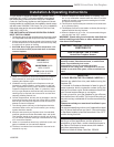
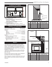
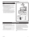
Fig. 5 Gas shutoff valve and flex connector.
When using copper or flex connector, use only ap-
proved fittings. Always provide a union when using
black iron pipe so that the gas line can be easily discon-
nected for burner or fan servicing. Refer to the gas
specification for pressure details and ratings.
Isolate or disconnect this or any other gas appli-
ance control from the gas line when pressure test-
ing.
DO NOT subject the fireplace valve to test
pressures exceeding 1/2 psi.
EB-1 Electrical Junction Box Connection
The fireplace, when installed, must be
electrically connected and grounded in ac-
cordance with local codes; in the absence
of local codes, use the current CSA C22.1
Canadian Electrical Code.
For USA installations, follow the local
codes and National Electrical Code ANSI/
NFPA No. 70.
It is strongly suggested the wiring of the
EB-1 Electrical Junction Box be carried out
by a licensed electrician.
Ensure power to the supply line has been
disconnected before commencing with this
procedure.
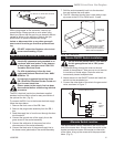
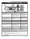
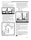
The EB-1 electrical junction box has been supplied
standard on this model to allow for easy connection of
the optional fan kits. (Fig. 6)
To connect the EB-1 box to the house electrical supply
follow the steps below.
1. Remove the front cover of the EB-1 box.
2. Remove the plug socket assembly from the EB-1
box.
3. Feed the supply line in from the out through the elec
-
trical knockout.
4. Connect the ground wire of the supply line to the
green screw of the socket assembly.
5. Connect the white wire of the power line to the
chrome screw of the socket assembly.
6. Connect the black wire of the power supply line to
the brass screw (polarized) of the socket assembly.
FP1428
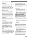
EB-1 location
Electrical
Inlet Hole
Gas Inlet
Hole
EB-1 Electrical box Depend-
ing on the specific model,
this box may be installed on
either side of the appliance.
FP1428
Fig. 6 EB-1 attachment.
Remote ON/OFF Switch Installation
Do not wire the remote ON/OFF wall switch
for this gas appliance into a 120V power
supply.
1. Thread the wiring through the holes on the end
panels of the appliance. Take care not to cut the wire
or insulation on metal edges. Route the wire to a
conveniently located receptacle box.
2. Attach the wire to the ON/OFF switch and install the
switch into the receptacle box.
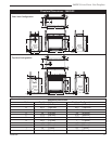
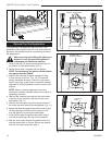
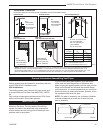
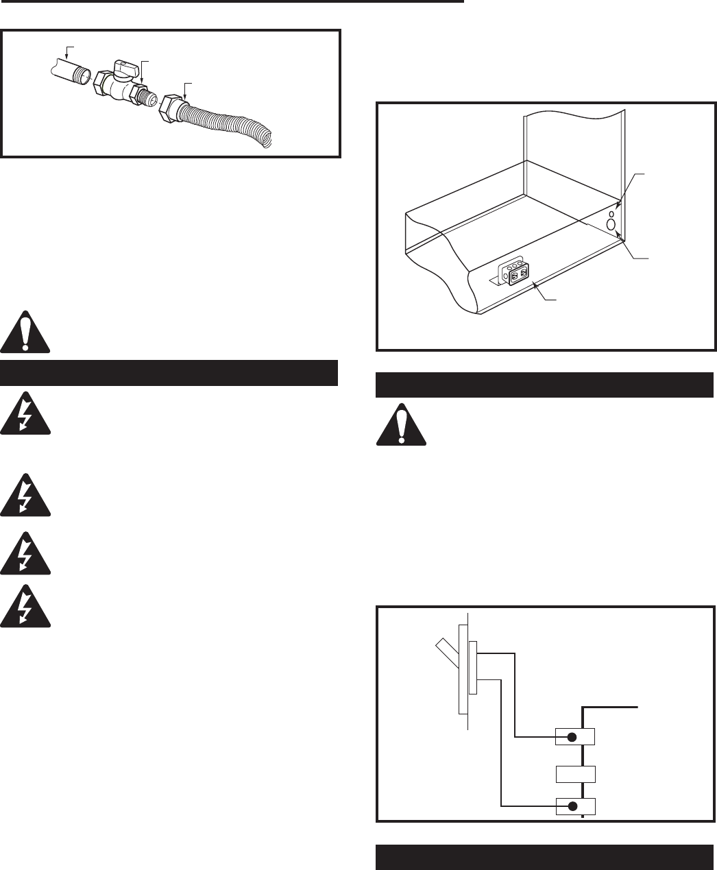
3. Connect the other ends of the wire to the gas control
valve, as shown in Figure 7.
TP
TH
TP
TH
FP1429
remote switch wiring
7/05
Remote ON/OFF Switch
Gas
Control
Valve
FP1429
Fig. 7 Remote switch wiring diagram for R models.
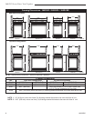
Alternate Switch Location
The remote switch can be installed on the front or the
side of the access door. Simply mount the switch to the
bracket provided and screw the bracket to either side
of the frame, lining up the screws with the prepunched
holes. (Fig. 8)
7. Refit the socket assembly back into the electrical
box and replace the cover plate.
8. The EB-1 electrical junction box is now ready to sup
-
ply power to the FK12 or FK24 fan kit, if used.