


13
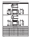
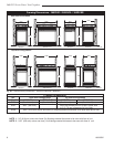
360DVS Series Direct Vent Fireplaces
10006326
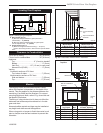
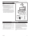
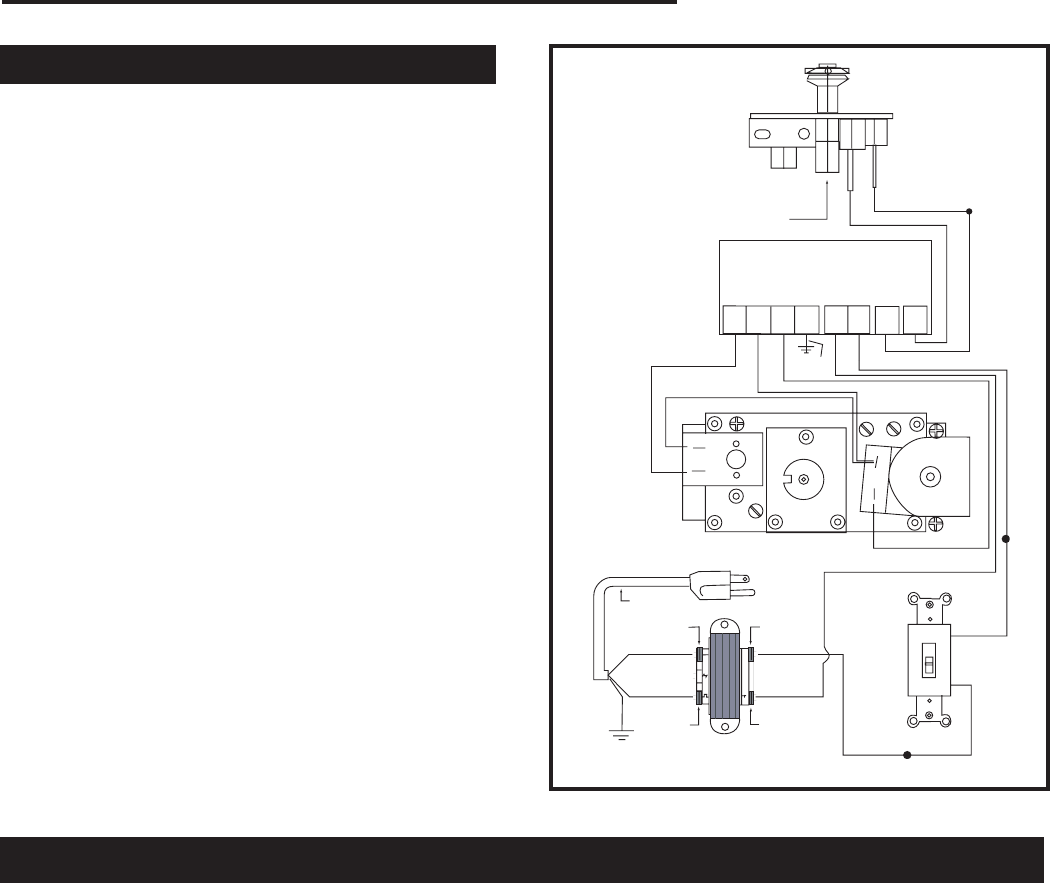
Electronic Gas Control Valve
This appliance may be fitted with a Honeywell ignition
module.
Installation of the remote ON/OFF starter switch on
electronic ignition units (Fig. 12):
1. Thread the wiring through the holes on the side
panels of the appliance. Take care not to cut the wire
or insulation on metal edges. Route the wire to a
conveniently located receptacle box.
2. Attach the wire to the ON/OFF switch and install the
switch into the receptacle box.
3. Connect the white wire from the wall switch to the
black wire from the transformer, using an approved
wire nut. Connect the black wire from the wall switch
to the black wire running from the #6 position of the
ignition module, also using an approved wire nut.
PILOT
HONEYWELL IGNITION MODULE
ORANGE
BLUE
BLACK
WHITE
NOVA SIT 822 VALV
E
HI
LO
POWER CORD
W/FEMALE SPADE
120 VAC RTN
WHITE
GREEN
BLACK
120 VAC HOT
BLACK
YELLOW
24 VAC RET
40VA TRANSFORMER
24 VAC HOT
BLACK
WHITE
WALL SWITCH
WHITE
OFF
1 2 3 5 6 8 9
MV MV/VP PV GRD 24V SENSE SPARK
24V
ORANGE
RED
GREEN
BLACK
FP1225
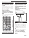
Fig. 12 Honeywell ignition module.
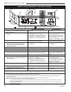
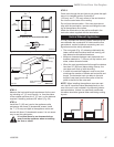
Your fireplace is approved to be vented either through
the side wall, or vertically through the roof.
• Only CFM Corporation venting components, specifi-
cally approved and labeled for this fireplace, may be
used.
• Venting terminals shall not be recessed into a wall or
siding.
• Horizontal venting must be installed on a level plane
without an inclining or declining slope.
There must not be any obstruction such as bushes,
General Venting
garden shed, fencing, deck or utility building within 24”
(610mm) from the front of the termination hood.
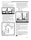
Do not locate the termination hood where excessive
snow or ice buildup may occur. Be sure to check the
vent termination area after snow falls; clear it to prevent
accidental blockage of the venting system. When using
a snow blower, make sure snow is not directed toward
the vent termination area.
Location of Vent Termination
It is imperative the vent termination be located observ-
ing minimum clearances as shown on the following
page.