


10
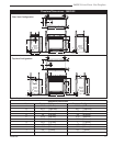
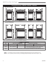
360 DVS Series Direct Vent Fireplaces
10006326
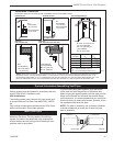
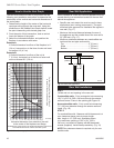
A hearth is not mandatory; however, for aesthetic
purposes, we recommend installing a noncombustible
hearth that projects out 12” (305mm) or more from the
front of the fireplace.
Cold climate installation recommendation:
When installing this unit against a noninsu-
lated exterior wall or chase, it is mandatory
the outer walls be insulated to conform to
applicable insulation codes.
Hearth
Final Finishing
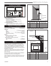
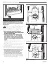
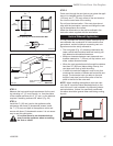
1. Choose the unit location.
2. Place the unit into position and secure it to the floor
with 1¹⁄₂” (38mm) screws or nails. Holes to secure
the unit to the floor are located behind the access
door grille on the left and right sides of the unit.
3. Frame in the fireplace with a header across the top.
It is important to allow for the finished wall face when
setting the depth of the frame.
4. Drywall (sheetrock) or wood material may be placed
with a zero clearance to the top edges of the appli-
ance when finishing walls above sides of the appli-
ance with glass windows. NOTE: Attach wall finish-
ing to constructed frame, not the appliance.
5. On 360DVSL and 360DVSR, drywall, wood, or wood
molding may be placed with zero clearance to the
rear wall of the unit, along the vertical edge formed
by the standoffs, to intersection of the rear wall, to
the side wall having the small glass window. NOTE:
Attach wall finishing to constructed frame, not
the appliance.
Framing & Finishing
Noncombustible materials such as brick or tile may be
extended over the edges of the face of the appliance.
DO NOT cover any vent or grille panels.
If a Trim Kit is going to be installed on the fireplace, the
brick or tile will have to be installed flush with the edges
of the appliance.
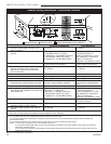
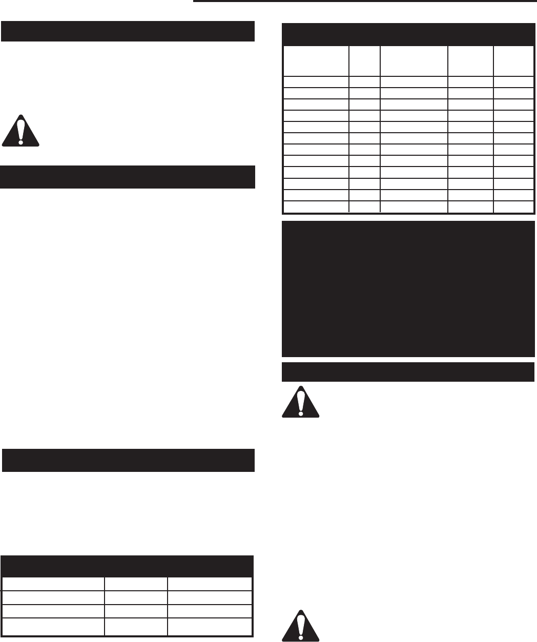
Max. Min.
Input Input
Model Fuel Gas Control BTU/h BTU/h
360DVS2RN Nat Millivolt 38,000 26,600
360DVS2RP Prop Millivolt 38,000 28,500
360DVS2EN Nat 24V Hi/Lo 38,000 26,600
360DVS2EP Prop 24V Hi/Lo 38,000 28,500
360DVS3RN Nat Millivolt 38,000 26,600
360DVS3RP Prop Millivolt 38,000 28,500
360DVS3EN Nat 24V Hi/Lo 38,000 26,600
360DVS3EP Prop 24V Hi/Lo 38,000 28,500
360DVSLRN Nat Millivolt 38,000 26,600
360DVSLRP Prop Millivolt 38,000 28,500
360DVSRRN Nat Millivolt 38,000 26,600
360DVSRRP Prop Millivolt 38,000 28,500
Gas Specifications
Gas Inlet & Manifold Pressures
Natural LP (Propane)
Inlet Minimum 4.5” w.c. 11.0” w.c.
Inlet Maximum 14.0” w.c. 14.0” w.c.
Manifold Pressure 3.5” w.c. 10.0” w.c.
Input ratings are shown in BTU per hour and are
certified without deration for elevations up to
4,500 feet (1,370 m) above sea level.
For elevations above 4,500 feet (1,370 m) in USA,
installations must be in accordance with the
current ANSI Z223.1/NFPA 54 and/or local codes
having jurisdiction.
In Canada, please consult provincial and/or local
authorities having jurisdiction for installations
above 4,500 feet (1,370 m).
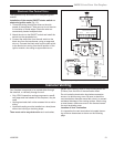
When purging the gas lines, the window
frame assembly must be removed.
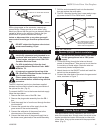
The gas pipeline can be brought in through the vent
end of the fireplace as well as the bottom. Knockouts
(to allow gas pipe installation and testing any gas con-
nection) are provided on the bottom behind the valve.
It is most convenient to bring the gas line in from the
vent end of the valve, as this allows fan installation or
removal without disconnecting the gas line.
The gas line connection can be made with properly
tinned 3/8” copper tubing, 3/8” rigid pipe, or an ap-
proved flex connector. Since some municipalities have
additional local codes, it is always best to consult your
local authority and the CSA-B149.1 installation codes.
For USA installations, consult the current National Fuel
Gas Code, ANSI Z223.1/NFPA 54.
Always check for gas leaks with a mild
soap and water solution. Do not use an
open flame for leak testing.
The gas control is equipped with a captured-screw type
pressure test point, therefore it is not necessary to pro-
vide a 1/8” test point upstream of the control.
Gas Line Installation