


39
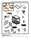
360DVS Series Direct Vent Fireplaces
10006326
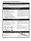
Optional Accessories
Fan Kits
FK24 Fan Assembly
This auxiliary fan system increases the efficiency of the
circulation of the heated air.
The FK24 fan kit allows variable speed control of the
circulation fan and also incorporates a heat sensor in
the circuit.
Specifications
115 Volt / 60Hz / 56 Watts
Maintenance
The fan itself does not require regular maintenance,
however periodic cleaning of the fan and the surround-
ing area is required.
Check the area under the control door (lower louvre as-
sembly) and in front of the fan and wipe or vacuum this
area at least once a month during the operating season.
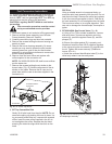
Installation
The fan assembly and other components are supplied
fully wired, eliminating the need for a licensed electri-
cian to carry out the installation.
If hard wiring the fan in using Method B (following) we
strongly recommend the use of a licensed electrician.
1. Open the lower louvre assembly. Maneuver the fan
and bracket assembly around the gas valve and
lines to locate the unit onto the screw studs on the
back of the fireplace.
2. Install the thermal sensor under the bottom of the
firebox, locating it over the two (2) 10 mm studs, and
secure it with nuts.
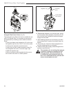
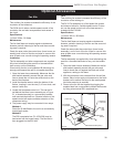
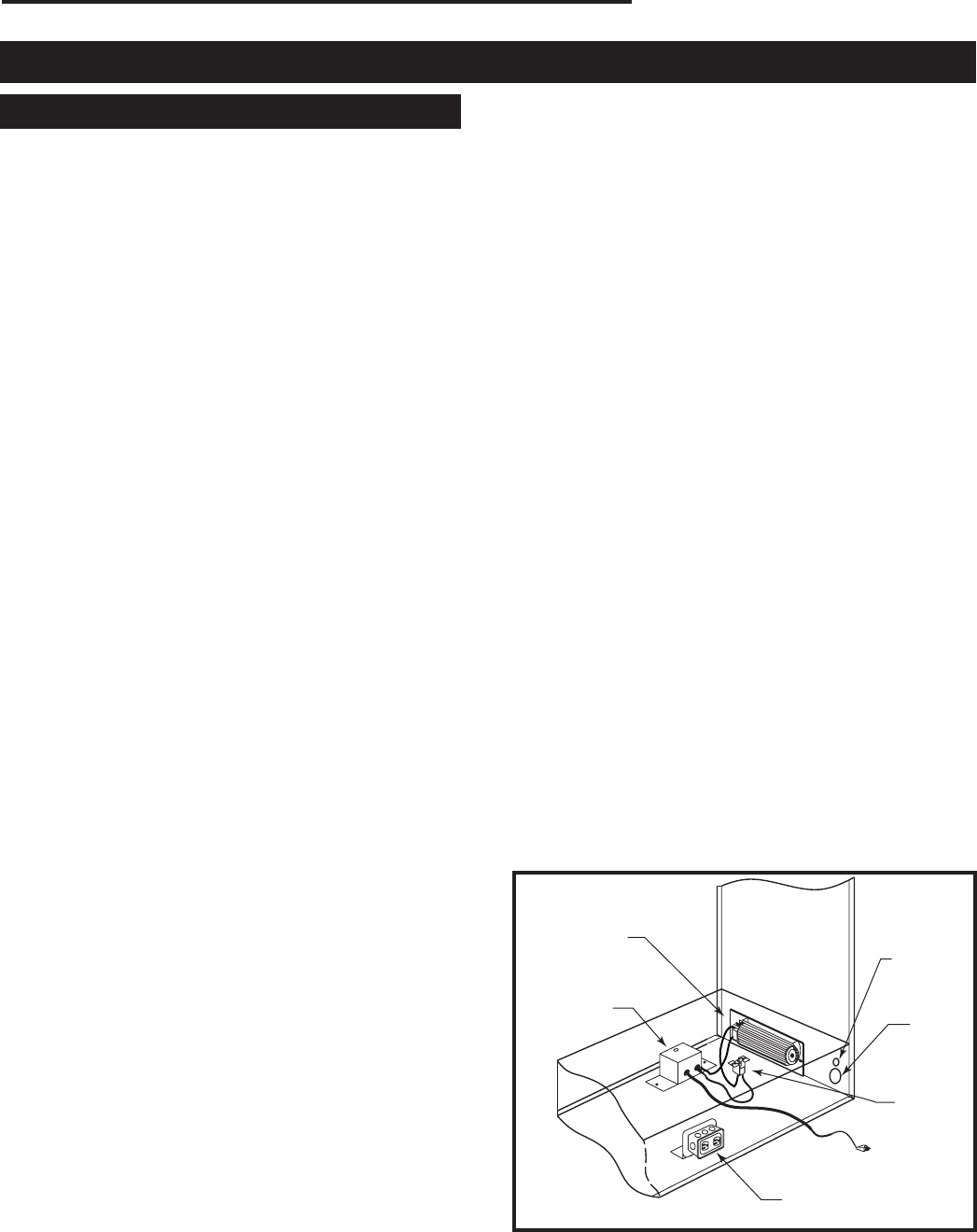
3. Locate the fan speed control unit. This can be fit
-
ted behind the lower louvre assembly as in Figure
51, or located remotely in a conveniently located
wall mounted electrical box. Remote location of the
speed control will require suitable extension of the
component wiring.
4. The power supply may be connected in two ways:
Method A
Route the 6’ lead fitted to the unit to a conveniently
located wall socket.
Method B
The EB-I receptacle box (Pt. # ZA1200) may be
hard-wired into the house supply. The fan lead is
then plugged into the EB-I box.
FK12
This auxiliary fan system increases the efficiency of the
circulation of the heating air.
The FK12 Fan Assembly is a fixed speed fan system
and does not allow for variable speed control. It does
not use the speed control unit or the heat sensor in-
cluded with the FK24 Kit.
Specifications
115 Volts / 60 Hz / 56 Watts.
Maintenance
The fan itself does not require regular maintenance;
however, periodic cleaning of the fan and the surround-
ing area is required.
Check the area under the control door (lower louvre
assembly), and in front of the fan. Wipe or vacuum this
area at least once a month during the operating season.
Installation
The fan assembly is supplied fully wired eliminating the
need for a licensed electrician to carry out the installa-
tion.
1. Open the lower Louvre assembly. Maneuver the fan
and bracket assembly around the gas valve and
lines to locate the unit against the back wall of the
appliance, resting on the base.
2. With the protective cover removed from the self-ad
-
hesive ‘Velcro’ strips apply mild pressure to the fan &
bracket unit to secure the strips to the metal panels.
No further securing is required.
3. Power to the fan can be supplied by plugging the
supplied lead into a conveniently-located wall socket
by using a hard-wired EB-I receptacle box.
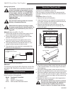
FP1448
Fan kit
multi sided
FK24 Fan
Fan Speed
Control Box
Electrical
Inlet Hole
Gas
Inlet
Hole
Electrical Box (EB-1)
Heat
Sensor
FP1448
Fig. 51 Fan installation.