


18
360 DVS Series Direct Vent Fireplaces
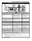
10006326
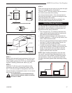
Horizontal plane means no vertical rise exists on this
portion of the vent assembly.
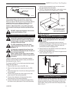
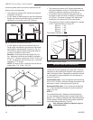
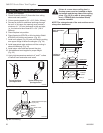
• The maximum number of 90˚ elbows per side wall
installation is three (3).
• If a 90˚ elbow is fitted directly on top of the fireplace
flange, the maximum horizontal vent run before the
termination or a vertical rise is 36” (914mm).
Max. 20”
(508mm)
Max. 36”
(914mm)
FP1436
Fig. 21 Maximum horizontal run w/no rise.
• If a 90° elbow is used in the horizontal vent run
(level height maintained), the maximum horizontal
vent length is reduced by 36” (914 mm). (Fig. 21)
This does not apply if the 90° elbows are used to
increase or redirect a vertical rise.
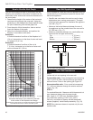
Example: According to the vent graph (Fig. 16),
the maximum horizontal vent length in a system
with a 7¹⁄₂” (191mm) vertical rise is 20 ft. (6.1m), but
if a 90° is required in the horizontal vent, it must be
reduced to 17 ft. (5.2m).
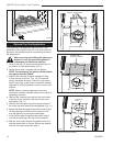
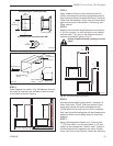
NOTE: The sum of Dim. A and Dim. B must not be
greater than 17 ft. (5.2m). (Fig. 22)
Elbow 1 = 90°
Elbow 2 = 45°
Elbow 3 = 45°
Elbow 4 = 90°
Total angular variation = 270°
A
B
90
o
FP1437
Fig. 22 Horizontal run reduction.
A + B = 17’
(5.2m) Max.
7’6” (2.3m)
• The maximum number of 45° elbows permitted per
side wall installation is two (2). These elbows can be
installed in either the vertical or horizontal run.
• For each 45° elbow installed in the horizontal run,
the length of the horizontal run MUST be reduced by
18” (45 cm). This does not apply if 45° elbows are
installed on the vertical part of the vent system.
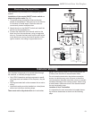
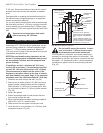
• The maximum number of elbow degrees in a system
is 270°. Example shown in Figure 23:
1
2
3
4
1
2
3
4
1 + 2 + 3 + 4 = 270°
FP1438
Fig. 23 Maximum elbow usage.
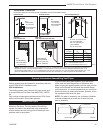
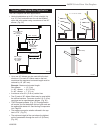
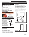
Vertical Side Wall Installation
STEP 1
Locate and cut vent opening in the side wall. It may be
necessary to first position the fireplace and measure to
obtain the hole location. Depending on whether the wall
is combustible or noncombustible, cut the opening to
size per Figure 24.
Combustible walls: Cut a rectangular hole measuring
9³⁄₈” H x 9³⁄₈” W (240 x 240mm) through the exterior wall
and frame. Frame in the opening per Figure 24.
Noncombustible walls: Cut a round hole measuring
7¹⁄₂” (190 mm) diameter through the exterior wall and
frame. (Fig. 24)
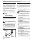
STEP 2
For combustible walls: Measure wall thickness and
cut zero clearance sleeve parts to proper length. Max.
length is 12” (305mm). Assemble the sleeve and attach
it to the firestop with #8 sheet metal screws (supplied).
Install the firestop assembly. (Fig. 25)
Zero clearance sleeve is required only for
combustible walls.