


20
360 DVS Series Direct Vent Fireplaces
10006326
2” (51 mm). Secure termination to the wall with screws
provided, and caulk around the wall plate to weather-
proof.
One alternative to screwing the termination directly to
the wallis the use of expanding plugs or an approved
exterior construction adhesive.
Or, you may attach the termination with screws through
the inner body into the 4” (102 mm) vent pipe; however,
for this method, you must extend the 4” (102mm) pipe
approximately 6” (153 mm) beyond the outer face of the
wall.
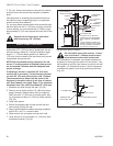
Support the horizontal pipes with metal
pipe straps every 36” (914mm).
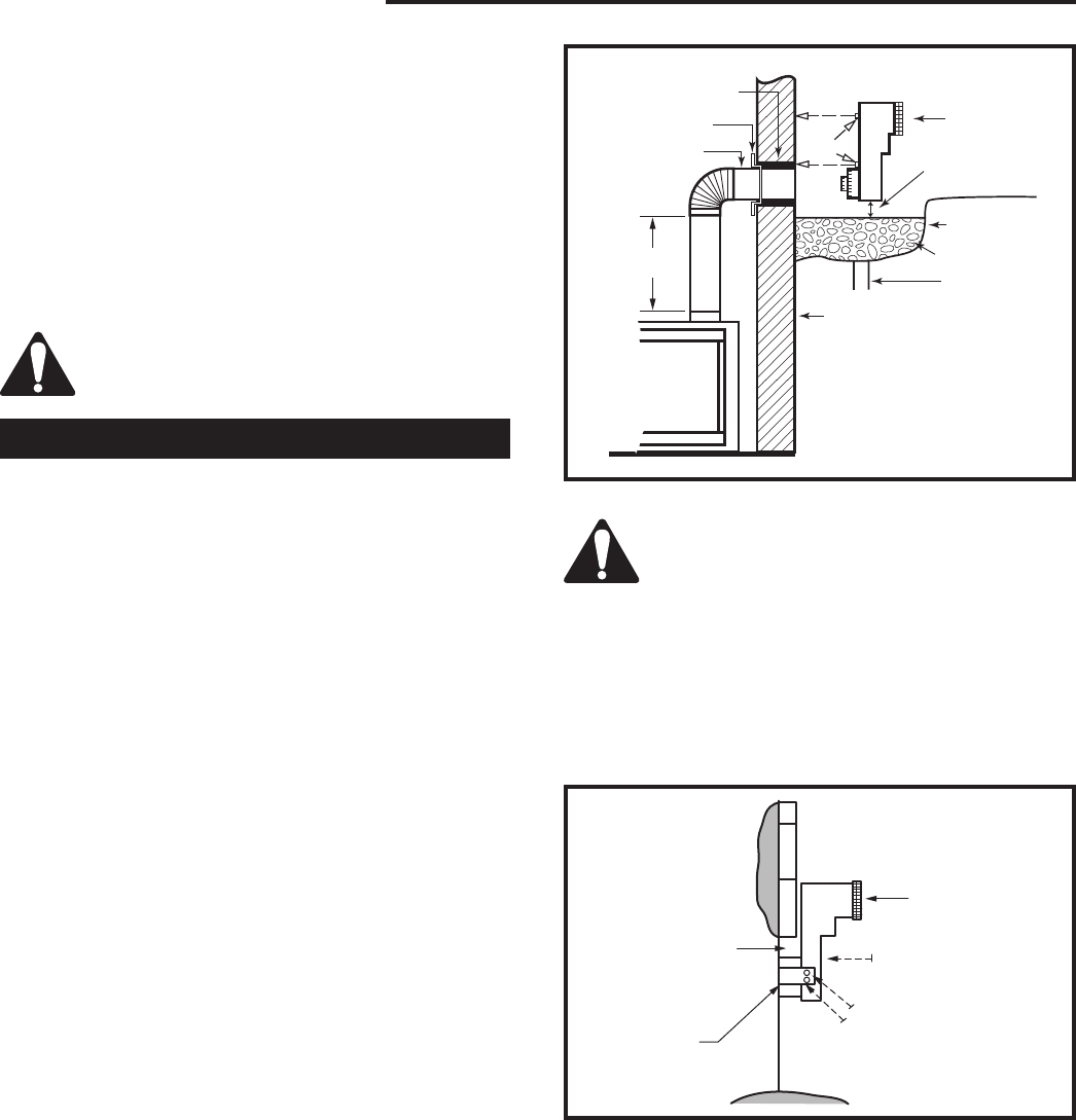
Below Grade Installation
When it is not possible to meet required vent terminal
clearances of 12” (305 mm) above grade level, we rec-
ommend using a starter kit. It allows installation depth
down to 7” (178 mm) below grade level. Measure 7”
(178 mm) from the center of the horizontal vent pipe as
it penetrates through the wall.
NOTE: Ensure sidewall venting clearances are ob
-
served. If venting system is installed below ground,
we recommend a window well with adequate and
proper drainage.
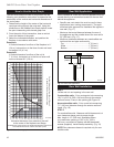
If installing a snorkel, a minimum 24” (610 mm)
vertical rise is necessary. The maximum horizontal
run with 24” (610 mm) vertical pipe is 36” (914mm).
The measurement is taken from the collar of the
fireplace (or transition elbow) to the face of exterior
wall. See sidewall vent graph, Page 15, for extended
horizontal runs if the vertical exceeds 24” (610 mm).
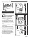
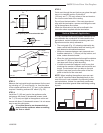
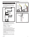
1. Establish vent hole through the wall. (Fig. 24)
2. Remove soil to depth of about 16” (406 mm) below
base of snorkel. Install window well (not supplied).
Refill hole with 12” (305 mm) of coarse gravel, leav-
ing a clearance of about 4” (102 mm) below snorkel.
(Fig. 28)
3. Install vent system.
4. Ensure a watertight seal is made around the vent
pipe coming through the wall.
5. Apply high-temperature sealant caulking (supplied)
around 4 in. and 7 in. snorkel collars.
6. Slide snorkel into vent pipes and secure to wall.
7. Level the soil so as to maintain a 4” (102 mm) clear
-
ance below snorkel. (Fig. 29)
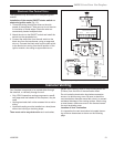
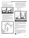
Zero Clearance
Sleeve (if required)
Firestop
7” Pipe
24” (610mm)
Minimum
Screws
7TDVSNORK
(Snorkel)
Min. 4” (102mm)
Clearance
(Ground)
Window Well
Gravel
Foundation Wall
Drain
• A minimum of 24” (610mm)
vertical pipe must be installed
when using the 7TDVSNORK
Kit.
• The 22” (559mm) vertical rise
(center to center) of the snorkel
may be included for calculation
of maximum horizontal run.
FP1442
Fig. 28 Below grade installation.
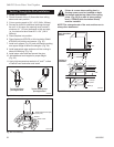
Do not backfill around the snorkel. A clear-
ance of at least 4” (102mm) must be main-
tained between the snorkel and the soil.
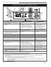
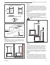
If the foundation is recessed, use recess brackets (not
supplied) for securing lower portion of the snorkel. Fas-
ten brackets to wall first, then secure to snorkel with self
drilling #8 x 1/2 sheetmetal screws. It will be necessary
to extend vent pipes out as far as protruding wall face.
(Fig. 29)
CFM139
Snorkel
2/26/01 sta
rev. 9-25-02 rjs
Snorkel
Foundation Wall
Watertight Seal
Around Pipe
Wall Screws
Sheet Metal Screws
CFM139
Fig. 29 Snorkel installation / recessed foundation.