


Installation & Operation Manual
70
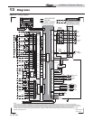
Figure 13-1 Wiring Diagram
13 Diagrams
DISPLAY
X1-8
X5-5
X5-13
X5-6
X5-12
INTEGRATED CONTROL
BLOWER
X1-1
X2-2
X2-1
X1-7
GAS
VALVE
FLAME
ROD
SPARK
ROD
W/R
G
R
R
T
W
BK
G
R
13
2
W
G
BOX DEPICTS
OPTIONAL ITEMS
WIRING DIAGRAM
LBL2364 REV D
INLET
SENSOR
OUTLET
SENSOR
FLUE
SENSOR
MANUAL RESET
HI-LIMIT
BLOCKED
DRAIN
X5-8
X5-1
X5-2
X5-9
X5-7
X5-14
X5-11
X5-3
X5-4
X5-10
BK
R
W
Y
BL
PR
OR
P
GY
BL
PR
OR
P
BL
1
245
3
SYSTEM
SENSOR
(AUX) DWH
TANK
SENSOR
OUTDOOR
SENSOR
0-10V
+
-
RS485
A
B
CONNECTION BOARD
CN3
X4
X1-3
X1-2
X1-6
X1-4
OR
PR
BK
BR
BK
W
ON/OFF
SWITCH
SHIELD
SHIELD
BK
Y
FLOW
SWITCH
GAS
PRESSURE
SWITCH
AUX.
DEVICE
PROVING
LOW
WATER
CUT-OFF
CN5-1
CN4-6
CN4-1
CN4-9
CN4-3
CN4-2
X6-9
X6-3
X6-4
X6-5
X6-10
BR
Y
P
BK
OR
CN4-11
CN4-12
CN4-10
CN4-4
ALARM
CONTACTS
RUN-TIME
CONTACTS
X3-1
X3-3
X3-4
X3-2
R
R
PR
PR
AUX.
DEVICE
PILOT
SUPPLY
CN4-8
X6-8
Y
DHW
THERMOSTAT
CN4-5
X6-1
W
ROOM
THERMOSTAT
ZONE
CONTROL
CN4-7
CN4-13
X6-2
X6-6
BL
GY
R
EXTERNAL
CONTROL
CAUTION HIGH VOLTAGE SPARK LEAD
CN5-3
CN5-4
CN5-2
24 VAC
COM
TR1
X8
120 VAC
LOW VOLTAGE
HIGH VOLTAGE
X3
PC
INTERFACE
CN4-14
CN1-12
CN1-11
CN1-10
CN1-9
CN1-8
CN1-7
CN1-6
CN1-5
CN1-4
CN1-3
CN1-2
CN1-1
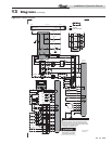
Notes:
1. All wiring must be installed in accordance with: local, state, provincial and national code requirements per either N.E.C. in USA or C.S.A. in Canada.
2. If any original equipment wire as supplied with the appliance must be replaced, it must be replaced with wire having same wi
re gauge (AWG) and rated for a
minimum of 105°C. Exceptions: Replacement high voltage spark lead and ribbon cables must be purchased from the factory. Use of a non-approved spark lead
or ribbon cables can lead to operational problems which could result in non-repairable damage to the integrated controller or other components.
3. Actual connector block locations may vary from those shown on diagrams. Refer to actual components for proper connector blo
ck locations when using
diagrams to troubleshoot unit.
CN2-1
CN2-2
CN2-3
CN2-4
CN2-5
CN2-6
CN2-7
CN2-8
CN2-9
CN2-10
CN2-11
CN2-12
CN2-13
CN2-14
CN2-15
CN2-16
CN1
CN2
CN5
CN4
CN3
BELL JUMPER
ALARM BELL
SILENCING SWITCH
S6
S4
S5
S2
S1
S3
OR
JUNCTION
BOX
120V
SUPPLY
GND
N
GND
L
SYSTEM
PUMP
BOILER
PUMP
DHW
PUMP
RELAY
BOARD
OR
OR
BR
BR
PR
PR
X1-5
W
CN2-4
CN2-2
CN2-3
CN2-1
K1
K2
K3
CN1-5
CN1-6
CN1-3
CN1-4
CN1-1
CN1-2
AIR PRESS. SWITCH
SOLENOID
VALVE
RELAY
RESISTOR