


Installation & Operation Manual
28
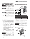
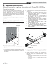
5 Vertical direct venting
Vent/air termination – vertical
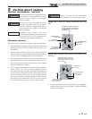
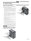
Prepare roof penetrations
1. Air pipe penetration:
a. Cut a hole for the air pipe. Size the air pipe hole as
close as desired to the air pipe outside diameter.
2. Vent pipe penetration:
a. Cut a hole for the vent pipe. For either combustible
or noncombustible construction, size the vent pipe
hole with at least a 1/2 inch clearance around the vent
pipe outer diameter:
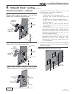
• 5½ inch hole (140 mm) hole for 4 inch (102 mm)
vent pipe
• 7½ inch hole (191 mm) hole for 6 inch (152 mm)
vent pipe
b. Insert a galvanized metal thimble in the vent pipe
hole (when required by local codes).
3. Space the air and vent holes to provide the minimum
spacing shown in FIG.’s 5-1A and 5-1B, page 27.
4. Follow all local codes for isolation of vent pipe when passing
through floors, ceilings, and roofs.
5. Provide flashing and sealing boots sized for the vent pipe
and air pipe.
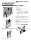
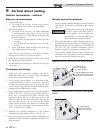
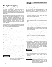
Termination and fittings
1. Prepare the vent termination coupling and the air
termination elbow (FIG.’s 5-1A and 5-1B) by inserting the
bird screens provided with the boiler.
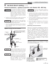
2. The air piping must terminate in a down-turned 180°
return bend as shown in FIG.’s 5-1A and 5-1B. Locate the
air inlet pipe no further than 2 feet (.6 m) from the center
of the vent pipe. This placement avoids recirculation of flue
products into the combustion air stream.
3. The vent piping must terminate in an up-turned coupling as
shown in FIG. 5-1A. The top of the coupling must be at
least 1 foot (.3 m) above the air intake. When the vent
termination uses a rain cap as illustrated in FIG. 5-1B
maintain at least 36" (914 mm) above the air inlet. The air
inlet pipe and vent pipe can be located in any desired
position on the roof, but must always be no further than
2 feet (.6 m) apart and with the vent termination at least
1 foot (.3 m) above the air intake.
4. Maintain the required dimensions of the finished
termination piping as shown in FIG.’s 5-1A and 5-1B.
5. Do not extend exposed vent pipe outside of building more
than shown in this document. Condensate could freeze and
block vent pipe.
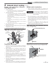
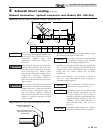
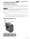
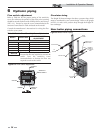
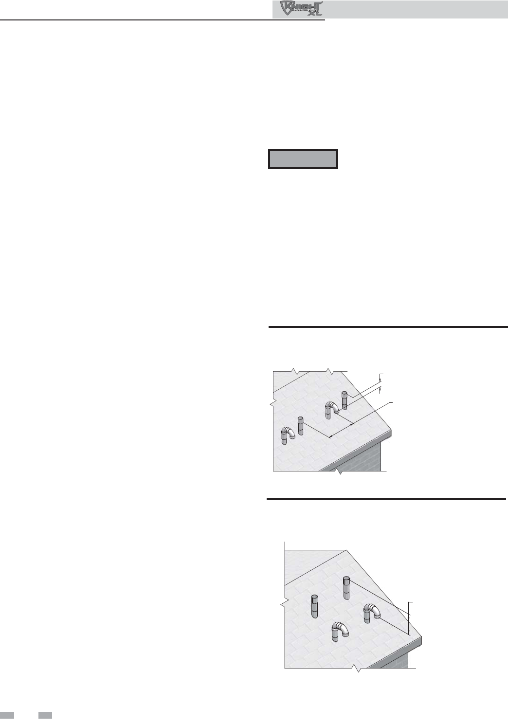
Multiple vent/air terminations
1. When terminating multiple Knight XL boilers, terminate
each vent/air connection as described in this manual
(FIG. 5-2).
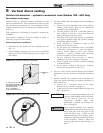
Terminate all vent pipes at the same height
and all air pipes at the same height to
avoid recirculation of flue products and
the possibility of severe personal injury,
death, or substantial property damage.
2. Place roof penetrations to obtain minimum clearance of
12 inches (305 mm) between edge of air intake elbow and
adjacent vent pipe of another boiler for U.S. installations
(see FIG. 5-2). For Canadian installations, provide
clearances required by CSA B149.1 Installation Code.
3. The air inlet of a Knight XL boiler is part of a direct vent
connection. It is not classified as a forced air intake with
regard to spacing from adjacent boiler vents.
12" (305 MM) MINIMUM
VERTICALLY FROM VENT
OUTLET TO ANY AIR INLET
12" (305 MM) MINIMUM FROM EDGE
OF AIR INTAKE PIPE TO ADJACENT
VENT PIPE FROM ANOTHER BOILER
AIR
AIR
VENT
VENT
Figure 5-2 Vertical Terminations with Multiple Boilers
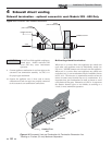
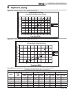
VENT
VENT
AIR
AIR
12" (305 MM) MINIMUM
VERTICALLY FROM VENT
OUTLET TO ANY AIR INLET
Figure 5-3 Alternate Vertical Terminations with Multiple
Boilers
ƽ WARNING