


Installation & Operation Manual
34
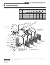
6 Hydronic piping
Circulator sizing
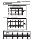
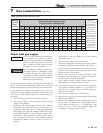
The Knight XL heat exchanger does have a pressure drop, which
must be considered in your system design. Refer to the graphs
in FIG’s 6-5 and 6-6 for pressure drop through the Knight XL
heat exchanger.
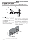
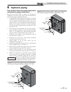
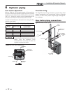
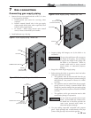
Near boiler piping connections
FROM
R
TO
INDIRECT
DOMESTIC
HOT WATER
TANK
TO FLOOR
DRAIN
TO
SYSTEM
FROM
SYSTEM
BOILER PUMP
DOMESTIC HOT
WATER PUMP
SYSTEM PUMP
Figure 6-4 Near Boiler Piping
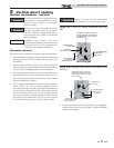
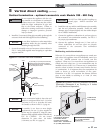
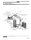
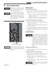
Figure 6-3 Flow Switch Adjustment
Flow switch adjustment
Refer to Table 6A for the proper setting of the sensitivity
screw. For reference, the position of the screw prior to setting
should be turned clockwise with a Phillips driver until it stops
(FIG. 6-3). Proceed to turn the screw counterclockwise the
amount of turns listed in Table 6A based on the model.
Consult the manufacturer’s instructions for wiring the flow
switch to your system.
NORMALLY
OPEN
SENSITIVITY
ADJUSTMENT
NORMALLY
CLOSED
COMMON
GROUND
NOTICE
Turn the sensitivity screw clockwise to
increase the flow rate required to activate the
switch. Turn the sensitivity screw
counterclockwise to decrease the flow rate
required to activate the switch.
MODEL PADDLE SIZE
SENSITIVITY SCREW
ADJUSTMENT
Note: Paddles are included with the flow switch.
399 #3 7½ turns
500 #3 5½ turns
600 #3 7¼ turns
700 #3 5¼ turns
800 #3 3¼ turns
Table 6A Paddle Size / Sensitivity Screw Adjustment