


Installation & Operation Manual
19
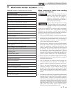
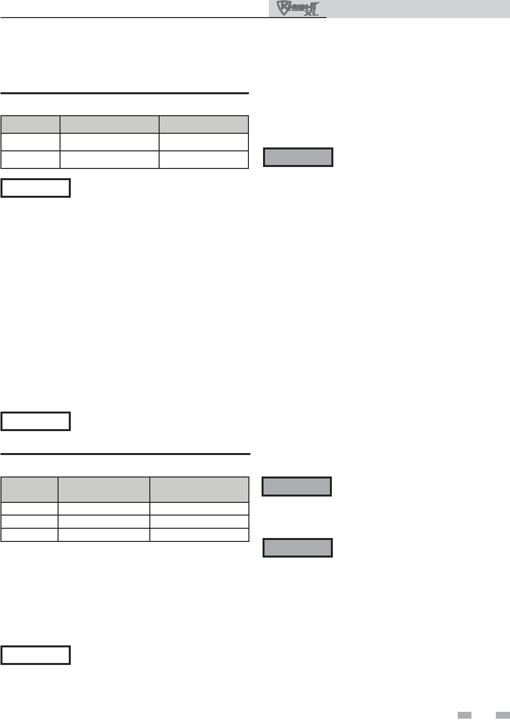
Model Kit Number
Equivalent
Vent Length
399 CVK3007 5 Feet (1.5 m)
500 CVK3007 30 Feet (9 m)
600 CVK3007 30 Feet (9 m)
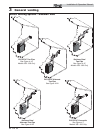
3 General venting (continued)
Vent, air piping and termination:
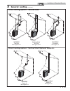
The Knight XL vent and air piping can be installed through the
roof or through a sidewall. Follow the procedures in this
manual for the method chosen. Refer to the information in this
manual to determine acceptable vent and air piping length.
Air contamination
Pool and laundry products and common household and hobby
products often contain fluorine or chlorine compounds. When
these chemicals pass through the boiler, they can form strong
acids. The acid can eat through the boiler wall, causing serious
damage and presenting a possible threat of flue gas spillage or
boiler water leakage into the building.
Please read the information given in Table 1A, page 11, listing
contaminants and areas likely to contain them. If
contaminating chemicals will be present near the location of the
boiler combustion air inlet, have your installer pipe the boiler
combustion air and vent to another location, per this manual.
If the boiler combustion air inlet is located
in a laundry room or pool facility, for
example, these areas will always contain
hazardous contaminants.
To prevent the potential of severe personal
injury or death, check for areas and products
listed in Table 1A, page 11 before installing
the boiler or air inlet piping.
If contaminants are found, you MUST:
• Remove products permanently.
—OR—
• Relocate air inlet and vent
terminations to other areas.
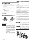
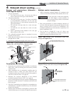
Removing from existing vent
Follow the instructions in Section 1, page 11 of this manual
when removing a boiler from an existing vent system.
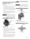
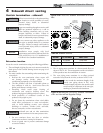
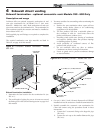
Vent and air piping
Vent and air system:
Installation must comply with local
requirements and with the National Fuel Gas
Code, ANSI Z223.1 for U.S. installations or
CSA B149.1 for Canadian installations.
You must also install air piping from outside to the boiler air
intake adapter. The resultant installation is direct vent (sealed
combustion).
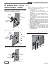
You may use any of the vent/air piping methods covered in this
manual. Do not attempt to install the Knight XL using any
other means.
DO NOT mix components from different
systems. The vent system could fail, causing
leakage of flue products into the living
space. Use only PVC or CPVC pipe and
fittings, with primer and cement specifically
designed for the material used.
NOTICE
ƽ WARNING
ƽ WARNING
ƽ WARNING
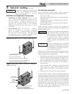
Table 3E Concentric Vent Kit Equivalent Vent Lengths
The appliance output rating will reduce by
up to 1.5% for each 25 feet (68 m) of vent
length.
NOTICE
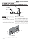
Minimum / Maximum allowable
combustion air and vent piping lengths are
as follows:
Combustion Air = 12 equivalent feet (3.7 m) minimum / 100
equivalent feet (30.5 m) maximum
Ven t = 12 equivalent feet (3.7 m) minimum / 100 equivalent
feet (30.5 m) maximum
When determining equivalent combustion air and vent length,
add 5 feet (1.5m) for each 90° elbow and 3 feet (.9 m) for each
45° elbow.
EXAMPLE: 20 feet (6 m) of PVC pipe + (3) 90° elbows + (3)
45° elbows + (1) concentric vent kit (CVK3007) = 49 equivalent
feet (15 m) of piping.
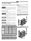
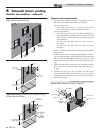
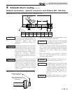
Model Air Intake Vent
399 - 600 4 inches (102 mm) 4 inches (102 mm)
700 - 800 4 inches (102 mm) 6 inches (152 mm)
The Knight XL uses model specific combustion air intake and
vent piping sizes as detailed in Table 3D below.
Table 3D Air Intake/Vent Piping Sizes
Increasing or decreasing combustion air or
vent piping is not authorized.
NOTICE