


Installation & Operation Manual
21
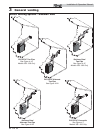
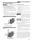
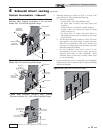
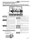
12" (305 MM) MIN
15" (381 MM) MAX
12" (305 MM) MIN
FROM BOILER
VENT PIPE
CONNECTION
TO BOILER
INTAKE AIR
CONNECTION
BIRD SCREEN
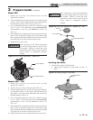
Figure 4-1C Alternate Vent Termination - Typical
Stainless Steel Sidewall Termination of Air and Vent
Models 399 - 600 w/Field Supplied Fittings
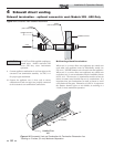
4 Sidewall direct venting (continued)
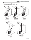
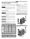
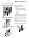
TO BOILER INTAKE
AIR CONNECTION
FROM BOILER VENT
PIPE CONNECTION
12" (305 MM) MIN
15" (381 MM) MAX
12" (305 MM) MIN
Figure 4-2B Alternate Stainless Steel Sidewall
Termination Models 700 - 800 w/Field Supplied Fittings
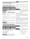
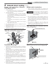
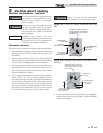
12" (305 MM) MIN
15" (381 MM) MAX
12" (305 MM) MIN
FROM BOILER
VENT PIPE
CONNECTION
TO BOILER
INTAKE AIR
CONNECTION
BIRD SCREEN
BIRD SCREEN
Figure 4-2A Alternate PVC/CPVC Sidewall Termination
Models 399 - 800 w/Field Supplied Fittings
PVC/CPVC or ABS is acceptable air inlet pipe material.
NOTICE
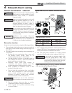
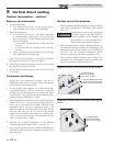
Vent/air termination – sidewall
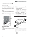
5. Maintain clearances as shown in FIG.’s 4-1A thru 4-4B,
pages 20 thru 22. Also maintain the following:
a. Vent must terminate:
• At least 6 feet (1.8 m) from adjacent walls.
• No closer than 12 inches (305 mm) below roof
overhang.
• At least 7 feet (2.1 m) above any public walkway.
• At least 3 feet (.9 m) above any forced air intake
within 10 feet (3 m).
• No closer than 12 inches (305 mm) below or
horizontally from any door or window or any other
gravity air inlet.
b. Air inlet must terminate at least 12 inches (305 mm)
above grade or snow line; at least 12 inches (305 mm)
below the vent termination (FIG. 4-1B); and the vent
pipe must not extend more than 24 inches (610 mm)
vertically outside the building.
c. Do not terminate closer than 4 feet (1.2 m)
horizontally from any electric meter, gas meter,
regulator, relief valve, or other equipment. Never
terminate above or below any of these within 4 feet
(1.2 m) horizontally.
6. Locate terminations so they are not likely to be damaged by
foreign objects, such as stones or balls, or subject to buildup
of leaves or sediment.
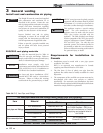
VENT / AIR
TERMINATION
12"
MIN.
12"
MIN.
12"
MIN.
Figure 4-3A Clearance to Gravity Air Inlets