


Installation & Operation Manual
45
8 Field wiring (continued)
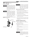
System supply sensor
1. By installing the system supply sensor into the supply of the
primary loop, the temperature of the system supply can be
controlled. The SMART SYSTEM control automatically
detects the presence of this sensor, and controls the boiler
firing rate to maintain the system supply temperature to the
set point (if the outlet sensor control is currently selected).
See the Knight XL Service Manual for instructions on how
to use the inlet sensor as the controlling sensor. When the
inlet sensor is programmed as the controlling sensor, it is
vital that the SYSTEM SUPPLY sensor be installed. DO
NOT INSTALL THE SYSTEM SUPPLY SENSOR INTO
THE SYSTEM RETURN.
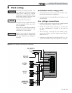
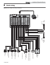
2. Connect these terminals to the system supply sensor
(FIG. 8-3).
Wiring of the cascade
When wiring the boilers for Cascade operation, select one
boiler as the Leader boiler. The remaining boilers will be
designated as Members. See page 53 “Configuration of the
Cascade” for a detailed explanation of this procedure.
Connect the system supply sensor and outdoor air sensor (if
used) to the Leader boiler. For the Cascade system to work
properly the system supply sensor must be installed. The
location of the system supply sensor should be downstream of
the boiler connections in the main system loop (FIG.’s 6-7 and
6-8). The system supply sensor should be wired to the Low
Voltage Connection Board at the terminals marked for the
system supply sensor (see FIG. 8-3). The Leader control will
use the water temperature at the system supply sensor to
control the operation of the Cascade.
If outdoor air reset is desired, the outdoor air sensor should be
wired to the Low Voltage Connection Board at the terminals
marked for the outdoor air sensor (FIG. 8-3). If the outdoor
air sensor is connected, the Leader control will calculate the
water temperature set point based on the programmed reset
curve parameters. If the outdoor air sensor is not connected,
the Leader control will maintain the fixed water temperature
set point that is programmed into the control.
If a Thermostat or Zone Control enable output is available, it
should be wired to the Low Voltage Connection Board on the
Leader boiler at the terminals marked for the Room
Thermostat/Zone Control (FIG. 8-3). If the boilers are to run
continuously, connect a jumper wire between the R and W
terminals for the Thermostat/Zone Control input. This will
initiate a call for heat on the Cascade.
Communication between the Leader boiler and the Member
boilers is accomplished by using shielded, 2-wire twisted pair
communication cable. Connect one of the twisted pair wires
to terminal A on each of the Low Voltage Connection boards,
and the other wire of the twisted pair to terminal B on each of
the Low Voltage Connection Boards. Connect the shield wires
to one of the shield ground terminals on the Low Voltage
Connection Boards (FIG. 8-3). If more than two boilers are
on the Cascade, daisy chain the wiring from the Sequencing
terminals on the second boiler to the Sequencing terminals on
the third boiler, then from the third to the forth, and so on.
The connections between boilers can be made in any order,
regardless of the addresses of the boilers. Try to keep each
cable as short as possible.
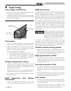
Boiler management system
1. An external control may be connected to control either the
firing rate or the set point of the boiler. Connect the Room
Thermostat / Zone Control terminals to the enable output
of the external control and connect the 0 - 10 VDC
terminals to the 0 - 10 VDC output of the external control.
2. Make sure the ground terminal is connected to the ground
output terminal of the external control, and the 0 - 10
VDC terminal is connected to the 0 - 10 VDC terminal of
the external control.
Runtime contacts
The SMART SYSTEM control closes a set of dry contacts
whenever the burner is running. This is typically used by
Building Management Systems to verify that the boiler is
responding to a call for heat.
Alarm contacts
The SMART SYSTEM control closes another set of contacts
whenever the boiler is locked out or the power is turned off.
This can be used to turn on an alarm, or signal a Building
Management System that the boiler is down. Note that these
contacts will close momentarily at the end of each call for heat
or at least every 24 hours.