


Installation & Operation Manual
12” (305 MM)
MIN
BIRD
SCREEN
(TYPICAL)
12” (305 MM)
MIN
12” (305 MM)
MIN
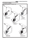
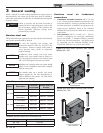
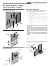
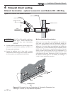
Figure 4-3B Alternate Clearance to Gravity Air
Inlets w/Field Supplied Fittings
36” (914 MM)
MIN
7’ (2.1 M) MIN ABOVE ANY
PUBLIC WALKWAY
IF LESS
THAN 10’ (3 M)
FORCED AIR
INLET
BIRD
SCREEN
(TYPICAL)
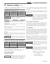
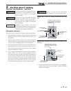
Figure 4-4B Alternate Clearance to Forced Air Inlets
w/Field Supplied Fittings
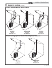
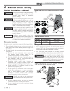
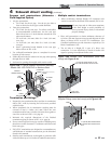
4 Sidewall direct venting
Vent/air termination – sidewall
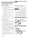
FORCED AIR
INLET
VENT / AIR
TERMINATION
7' MIN. ABOVE ANY
PUBLIC WALKWAY
IF LESS
THAN 10’
36"
MIN.
Figure 4-4A Clearance to Forced Air Inlets
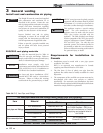
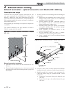
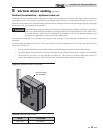
VENT PIPING
GALVANIZED
THIMBLE
VENT CAP
AIR PIPING
WALL PLATE
VENT PLATE
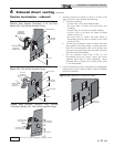
Figure 4-5A Sidewall Termination Assembly
Prepare wall penetrations
1. Use the factory supplied wall plate as a template to locate
the vent and air intake holes and mounting holes.
Air pipe penetration:
a. Cut a hole for the air pipe. Size the air pipe hole as
close as desired to the air pipe outside diameter.
Vent pipe penetration:
a. Cut a hole for the vent pipe. For either combustible or
noncombustible construction, size the vent pipe hole
with at least a 1/2 inch clearance around the vent pipe
outer diameter:
• 5½ inch hole (140 mm) hole for 4 inch (102 mm)
vent pipe
• 7½ inch hole (191 mm) hole for 6 inch (152 mm)
vent pipe
Drill 3/16" diameter holes for inserting the plastic anchors
into the wall.
2. Install the vent and air intake piping through the wall into
the vent plate openings. Seal all gaps between the pipes and
wall. Use RTV silicone sealant to seal the air pipe. Use the
cement/primer listed in Table 3A on page 16 to seal the vent
pipe.
3. Mount and secure the vent plate to the wall using stainless
steel screws. Seal around the plate to the wall assuring no
air gaps.
4. Assemble the vent cap to the vent plate (see FIG. 4-4A).
Insert the stainless steel screws into the vent cap screw hole
openings and securely attach the vent cap to the vent plate.
5. Seal all wall cavities.
22