


Installation & Operation Manual
44
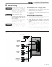
Low voltage connections
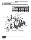
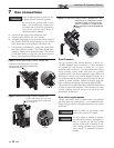
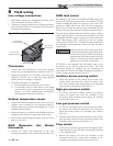
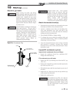
1. Route all low voltage wires through the knockouts in the
rear of the boiler, as shown in FIG. 8-2.
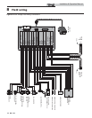
2. Connect low voltage wiring to the low voltage connection
board as shown in FIG. 8-3 on page 46 of this manual and
the boiler wiring diagram.
LOW VOLTAGE
WIRING KNOCKOUTS
LINE VOLTAGE
WIRING KNOCKOUTS
LOW VOLTAGE
CONNECTION BOARD
LINE VOLTAGE
JUNCTION BOX
Figure 8-2 Routing Field Wiring
8 Field wiring
Thermostat
1. Connect the room thermostat or end switch (isolated
contact only) to terminals R and W, as shown in FIG. 8-3.
2. Install the thermostat on the inside wall away from
influences of drafts, hot or cold water pipes, lighting
fixtures, television, sunlight, or fireplaces.
3. Thermostat anticipator (if applicable):
a. If connected directly to boiler, set for 0.1 amps.
b. If connected to relays or other devices, set to match
total electrical power requirements of connected
devices. See device manufacturers’ specifications
and thermostat instructions for details.
Outdoor temperature sensor
1. Connect the outdoor temperature sensor (FIG. 8-3) to the
Outdoor Sensor terminals on the connection board to
enable outdoor reset operation of the Knight XL. Do not
install the outdoor sensor.
2. Mount the sensor on an exterior wall, shielded from direct
sunlight or flow of heat or cooling from other sources.
3. Route sensor wires through a knockout at the rear of the
boiler (see FIG. 8-2).
DHW (Domestic Hot Water)
thermostat
1. Connect the DHW tank thermostat to the Tank
Thermostat terminals on the connection board (FIG. 8-3).
DHW tank sensor
By installing a tank sensor, the SMART SYSTEM control can
perform the tank thermostat function. The SMART SYSTEM
control automatically detects the presence of this sensor, and
generates a DHW call for heat when the tank temperature
drops 6°F (3°C) below the tank set point, and finishes the call
for heat when the tank temperature reaches the tank set point.
The tank sensor included with the Lochinvar Squire® indirect
DHW tanks (TST2032) is the only sensor suitable for use with
the SMART SYSTEM control. Connect the sensor leads to the
DHW Tank Sensor (AUX) terminals on the low voltage
connection board (FIG. 8-3). Consult the tank manufacturer
for application and performance when used with any other
indirect tank.
Auxiliary device proving switch
1. When the operation of an auxiliary device needs to be
verified before the boiler fires, remove the jumper wire
from these terminals and connect them to the normally
open contacts on its proving switch (FIG. 8-3).
High gas pressure switch
1. If a switch is provided to detect excessive gas pressure,
remove the jumper wire from the terminals on the
connection board, and then connect them to its normally
closed contacts (FIG. 8-3).
Low gas pressure switch
1. If a switch is provided to detect low gas pressure, remove
the jumper wire from the terminals on the connection
board and connect them to its normally open contacts
(FIG. 8-3).
2. If both a high and low gas pressure switch is used, connect
their respective contacts in series, and connect them to the
terminals on the connection board (FIG. 8-3).
Flow switch
1. A flow switch is used to guarantee flow through the boiler
before allowing it to fire. The flow switch must be installed
in line with the boiler.
2. Remove the jumper wire from the terminals on the
connection board and connect these terminals to the
normally open contacts on the flow switch (FIG. 8-3).
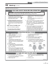
Failure to use the correct sensor may result
in the tank temperature being either above
or below the set point. Failure to consult the
manufacturer of the indirect tank, when the
Squire is not used, may result in decreased
performance or the risk of scald injury.
ƽ WARNING
If TST2032 is not compatible with the indirect tank, a tank
thermostat can be used to control the boiler. The tank
thermostat should be installed per the manufacturer’s
instructions and wired to the DHW Thermostat terminals on
the low voltage connection board (FIG. 8-3).