


Installation & Operation Manual
69
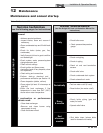
12 Maintenance (continued)
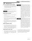
Check flame signal
1. At high fire the flame signal shown on the display should
be at least 10 microamps.
2. A lower flame signal may indicate a fouled or damaged
flame sense electrode. If cleaning the flame sense
electrode does not improve, ground wiring is in good
condition, and ground continuity is satisfactory, replace
the flame sense electrode.
3. See Section 3 - Troubleshooting in the Knight XL Service
Manual for other procedures to deal with low flame
signal.
Review with owner
1. Review the Knight XL User’s Information Manual with
the owner.
2. Emphasize the need to perform the maintenance
schedule specified in the Knight XL User’s Information
Manual (and in this manual as well).
3. Remind the owner of the need to call a licensed
contractor should the boiler or system exhibit any
unusual behavior.
4. Remind the owner to follow the proper shutdown
procedure and to schedule an annual start-up at the
beginning of the next heating season.
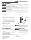
Cleaning boiler heat exchanger
1. Shut down boiler:
• Follow the “To Turn Off Gas to Appliance” instructions
for the boiler in Section 10 - Startup.
• Do not drain the boiler unless it will be exposed to
freezing temperatures. If using freeze prevention fluid
in system, do not drain.
2. Allow time for the boiler to cool to room temperature if
it has been firing.
3. Remove the blower assembly (gas air/arm) from the heat
exchanger access cover. Set bolts aside.
4. Remove the nuts securing the heat exchanger access cover
to the heat exchanger and set aside.
5. Remove the heat exchanger access cover, cover gasket(s)
and chamber insulation assembly.
The boiler contains ceramic fiber
materials. Use care when handling these
materials per instructions in the Handling
Ceramic Fibers Section of the Knight XL
Service Manual. Failure to comply could
result in severe personal injury.
6. Use a vacuum cleaner to remove any accumulation on the
boiler heating surfaces. Do not use any solvent.
7. Finish cleaning using a clean cloth dampened with warm
water.
8. Install access cover gasket, chamber insulation assembly
and cover.
9. Secure nuts on the studs. DO NOT overtighten.
10. Re-install the blower assembly (gas air/arm) using the
bolts set aside in Step 3.
11. Close isolation valves on piping to isolate boiler from
system. Attach a hose to the boiler drain and flush boiler
thoroughly with clean water by using purging valves to
allow water to flow through the water make-up line to the
boiler.
12. When the boiler has been flushed, restore boiler to
operation.
13. Perform start-up and check-out procedures in Section 10
- Startup.
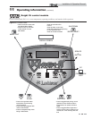
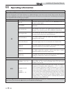
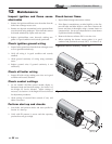
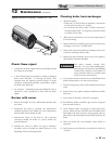
ƽ WARNING
AIR ARM
SCREWS
(QTY. 5)
GASKET
BURNER
Figure 12-4 Burner Assembly - Models 600 - 800