


Installation & Operation Manual
36
6 Hydronic piping
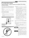
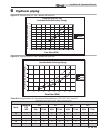
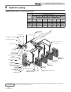
It is required that near boiler piping
systems utilize Primar y/Secondar y
configurations as shown in FIG.’s 6-7 and
6-8 only. The use of other near boiler
piping configurations could result in
improper building and system flow rates
leading to inadvertent boiler high limit
shutdowns and poor system performance.
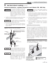
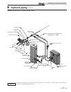
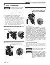
Near boiler piping components
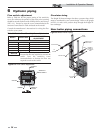
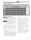
1. Boiler system piping:
Boiler system piping MUST be sized per the pipe
requirements listed in Table 6B. Reducing the pipe size
can restrict the flow rate through the boiler, causing
inadvertent high limit shutdowns and poor system
performance. Flow rates are based on 20 feet (6 m) of
piping, 4 - 90° elbows, and 2 - fully ported ball valves.
2. Boiler system circulating pump:
Field supplied. The boiler circulating pump should be
based on 20 feet (6 m) of piping, 4 - 90° elbows, and 2 -
fully ported ball valves.
3. Domestic hot water circulating pump:
Field supplied. The pump MUST be sized to meet
the specified minimum flow requirements listed in
FIG.’s 6-5 and 6-6. Consult the indirect water heater
operating guide to determine flow characteristics for the
selected product used.
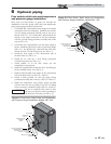
4. Boiler isolation valves:
Field supplied. Full port ball valves are required. Failure
to use full port ball valves could result in a restricted flow
rate through the boiler.
5. Check valves:
Field supplied. Check valves are recommended for
installation as shown in FIG.’s 6-7 and 6-8. Failure to
install check valves could result in a reverse flow condition
during pump(s) off cycle.
6. Domestic indirect hot water isolation valves:
Field supplied. Full port ball valves are
required. Failure to use full port ball valves could
result in a restricted flow rate through the boiler.
7. Anti-scald mixing valve:
Field supplied. An anti-scald mixing valve is
recommended when storing domestic hot water above
115°F (46°C).
8. Unions:
Field supplied. Recommended for unit serviceability.
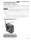
9. Temperature and pressure gauge:
Factory supplied. The temperature and pressure gauge is
shipped loose. It is the responsibility of the contractor to
install the temperature and pressure gauge on the boiler
water outlet.
10. Pressure relief valve:
Factory supplied. The pressure relief valve is sized to
ASME specifications.
11. Boiler purge valve:
Field supplied. The boiler purge valve is used to
remove entrapped air from the heat exchanger during
start-up.
12. System temperature sensor:
Lochinvar supplies a system temperature sensor.
The sensor is to be installed in the heating loop
downstream from the boiler hot water piping and
heating loop junction. The sensor should be
located far enough downstream to sense system diluted
water temperature.
NOTICE
Pump sizing and flow requirements are
based on 20 feet (6 m) of piping, 4 - 90°
elbows, and 2 - fully ported ball valves.
NOTICE