


55
3 Troubleshooting (continued)
Gas valve adjustment procedure
If adjustment of the gas valve is deemed necessary, use the
following procedures: (Note: The procedures below are
model specific.)
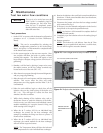
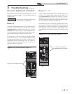
THROTTLE ADJUSTMENT SCREW
Figure 3-2 Gas Valve Adjustment: Model 1.0
Model 1.0
Locate the throttle adjustment screw on top of the gas valve,
see FIG. 3-2. Using a screwdriver, turn the screw a 1/4 turn
counterclockwise to increase CO
2
levels or a 1/4 turn
clockwise to decrease CO
2
levels. After one adjustment on
the valve, follow the Combustion Analysis Procedure on
page 54 of this manual to measure the combustion.
If combustion is still not within the specified range,
repeat the procedure. This procedure SHOULD NOT
be performed more than four (4) times. If after four (4)
adjustments and the combustion is still not within the
specified range, revisit the possible causes in Table 3G on
page 54 or replace the gas valve.
CAUTION
Under normal operating conditions this
valve should not need adjusting.
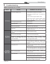
Models 1.3 - 1.5
Locate the throttle adjustment screw on top of the gas valve,
see FIG. 3-3. Using an Allen wrench, turn the screw a 1/4
turn counterclockwise to increase CO
2
levels or a 1/4 turn
clockwise to decrease CO
2
levels. After one adjustment on
the valve, follow the Combustion Analysis Procedure on page
54 of this manual to measure the combustion.
If combustion is still not within the specified range, repeat
the procedure. This procedure SHOULD NOT be performed
more than four (4) times. If after four (4) adjustments and
the combustion is still not within the specified range, revisit
the possible causes in Table 3G on page 54 or replace the gas
valve.
THROTTLE ADJUSTMENT
SCREW (REMOVE BLUE COVER)
Figure 3-3 Gas Valve Adjustment: Models 1.3 - 1.5
Service Manual