


41
2 Maintenance
Test low water flow conditions
NOTICE
This test is to be carried out once the
SYNC boiler is completely piped in
with adequate gas and water flow.
Once the test is completed, ensure
that the isolation valve is opened up to
allow full water flow.
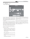
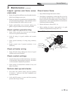
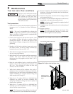
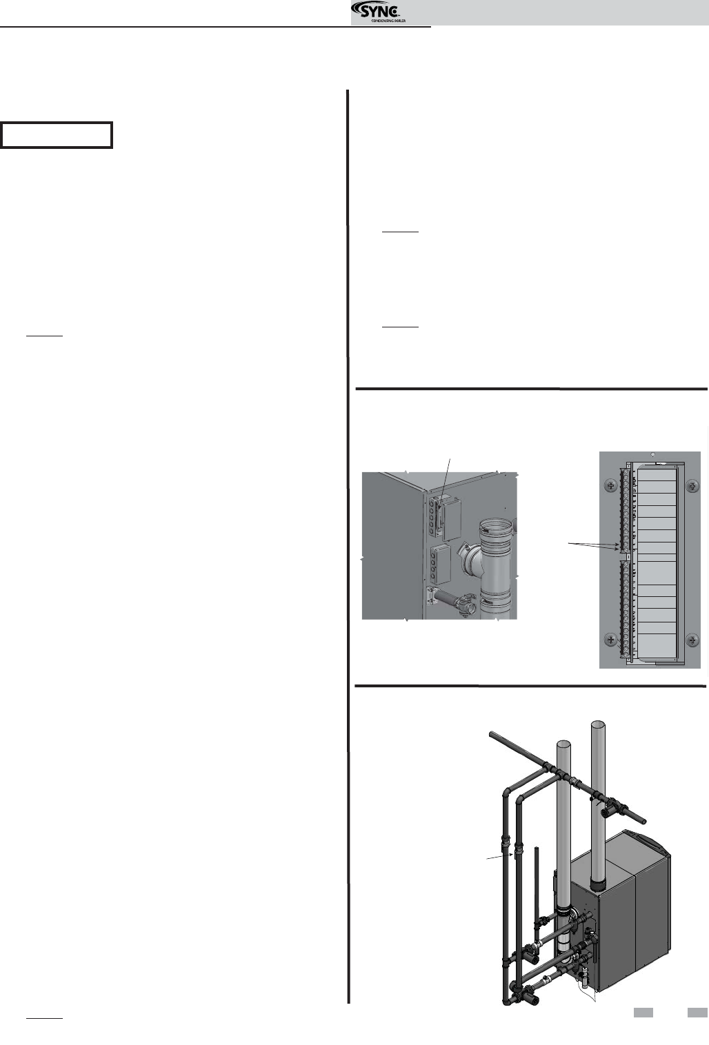
Figure 2-4 Adjust outlet isolation valve
Test procedure
1. Set the SYNC to operate with the demand configuration
parameter set to 1 (Cascade Set Point Thermostat-
Based).
NOTE: This can be accomplished by selecting the
demand configuration parameter in the Service/Setup
Menu. See Section 1 of this manual for complete details
of the SmartTouch controls.
2. Set the system setpoint to the max user setpoint. Max
user setpoint will allow the boiler to operate without
reaching this setpoint. The boiler will require a load
large enough to dissipate a large portion of the heat it is
generating.
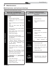
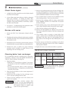
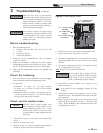
3. Simulate a call for heat by placing a jumper wire across
the enable contacts on the low voltage terminal strip
located at the rear of the unit (FIG. 2-3).
4. Allow the unit to progress through its normal diagnostics
and pre-purge programming.
5. Allow the unit to fire and operate until the temperatures
stabilize. This occurs when the inlet and outlet
temperatures are rising together and the Delta T (ࣼ T)
is maintained.
6. When the unit stabilizes, begin to slowly shut off the
isolation valve on the outlet piping of the boiler (see
FIG. 2-4). This will begin to restrict the flow and
simulate a low flow condition.
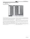
7. While slowly shutting off the isolation valve, refer to
the Burner Screen to watch the behavior of the boiler.
On this screen, you will witness each individual control
module modulating its’ respective burner’s firing rate
while reacting to the rising ࣼ T.
8. When the ࣼ T reaches 50˚F for an individual heat
exchanger, the control for the heat exchanger will
attempt to modulate the firing rate down to protect it
from low flow conditions.
9. When the ࣼ T reaches 60˚F for an individual heat
exchanger, the control module for the heat exchanger
will turn off the respective burner.
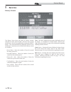
NOTE: The Temperature Menu will show the inlet and
outlet temperatures for each individual heat exchanger.
A
DJUST OUTLET
ISOLATION VALVE
ONLY
10. Restrict the isolation valve until both control modules have
shut down. If both control modules have been shut down,
the test was successful.
11. Disconnect the jumper wire from the low voltage terminal
strip connected in step 3.
12. If necessary, reset the demand configuration in the Service/
Setup Menu to the required operational mode.
NOTE: See Section 1 of this manual for complete details of
the SmartTouch controls.
13. Completely open the isolation valve on the outlet piping of
the boiler.
14. Resume operation.
NOTE: This lockout is a soft lockout. Once the ࣼ T has
decreased to an acceptable level and there is a call for heat,
the unit will fire again to meet the demand.
Figure 2-3 Low voltage terminal strip & enable contacts
LOW VOLTAGE CONNECTION BOARD
1 ALARM
LBL20052 REV B
30 SHIELD GND
MOD BUS
0 - 10V INPUT
2 CONTACTS
3 RUN TIME
4 CONTACTS
5 LOUVER
6 PROVING
7 MODULE 2
8 FLOW SWITCH
9 MODULE 1
10 FLOW SWITCH
29 A
26 SENSOR
25 TANK
24 SENSOR
23 OUT DOOR
22 SENSOR
21 SYSTEM
20 (-)
19 (+)
18 SHIELD GND
17 B
16 A
15 SHIELD GND
14 W
13 R
11 TANK
12 THERMOSTAT
28 B
27 SHIELD GND
CASCADE
ENABLE
ENABLE
CONTACTS
Service Manual