


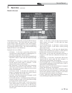
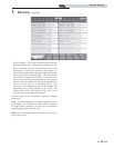

Service/Setup Parameters Screen:
1 Service (continued)
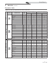
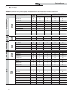
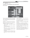
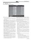
The Service / Setup Screen allows access to 10 parameters.
Those parameters are as follows:
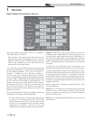
• Demand Configuration - Sets the configuration of the
control modules inside the boiler. The configuration
selections are:
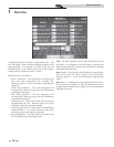
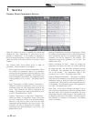
Demand Configuration 1: Cascade Set Point Thermostat
based - the control modulates the boiler based on the user
set point and the temperature of the controlling sensor. An
enable signal from a remote end switch or enabling device
must be present to initiate a system heat call.
Demand Configuration 4: Cascade Set Point Modbus
Thermostat based - the control modulates the boiler based
on the user set point and the temperature of the controlling
sensor. An enable signal is provided by writing to the
holding registers on the Modbus communication board.
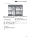
Demand Configuration 2: Cascade BMS Thermostat
based - a 0 - 10Vdc signal is provided to the boiler to
control either the set point or the modulation of the boiler.
An enable signal from a remote end switch or enabling
device must be present to initiate a system heat call.
Demand Configuration 5: Cascade Modbus BMS
Thermostat based - a 0 - 10V dc signal is provided to the
boiler to control either the set point or the modulation of
the boiler. An enable signal and an equivalent 0 - 10V signal
is provided by writing to the holding registers on the
Modbus communication board.
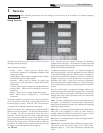
Demand Configuration 3: Cascade BMS Voltage based - a
0 - 10Vdc signal is provided to the boiler to control either
set point or modulation. A minimum voltage signal is
required to initiate a system heat call.
Demand Configuration 6: Cascade Modbus BMS Voltage
based - a 0 - 10V dc signal is provided to the boiler to
control either set point or modulation. An equivalent 0 -
10V dc signal is provided by writing to the holding registers
on the Modbus communication board.
If either BMS configuration is selected, additional parameters
for BMS operation will have to be adjusted. Reference
the BMS parameters on pages 27 and 28 for information
regarding adjusting these parameters. There are three (3) other
configuration selections that are possible, however, they must
NOT be used on the SYNC boiler.
This parameter can only be changed by the installer. The default
configuration is Cascade Set Point Thermostat based.
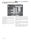
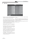
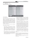
• Service Notification Time - When the boiler determines
that a scheduled service is due based on days of
installation, the Service Needed screen will appear. This
parameter can only be changed by the installer. The
adjustment range for this parameter is 0 months to 36
months. The default time is 12 months.
• Service Notification Running Hours - When the boiler
determines that a scheduled service is due based on the
hours of actual operation. This parameter can only be
changed by the installer. The adjustment range for this
parameter is 0 hours to 100,000 hours. The default time is
10,000 hours.
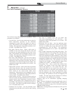
• Service Notification Cycles - When the boiler determines
that a scheduled service is due based on the number of
boiler cycles, the Service Needed screen will appear. This
parameter can only be changed by the installer. The range
for this parameter is 0 cycles to 100,000 cycles. The default
is 10,000 cycles.
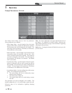
• Ramp Delay - Sets the mode of operation of the ramp delay.
The selections are:
0. Off - Ramp delay disabled.
1. Step Up - The total output of the boiler or cascade will
be limited after the call for heat begins.
2. Step Up / Down - The initial limitation will be
determined by how long the boiler or cascade has been
off. This parameter can only be changed by the
installer. The default value is 0 - Off.
19
Service Manual