


Inspect ignition and flame sense
electrodes
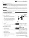
1. Remove the ignition and flame sense electrodes from the
boiler heat exchanger access cover.
2. Remove any deposits accumulated on the ignition/flame
sense electrode using sandpaper. If the electrodes cannot
be cleaned satisfactorily, replace with new ones.
3. Replace ignition/flame sense electrode, making sure
gasket is in good condition and correctly positioned.
Check ignition ground wiring
1. Inspect boiler ground wire from the heat exchanger
access cover to ground terminal strip.
2. Verify all wiring is in good condition and securely
attached.
3. Check ground continuity of wiring using continuity
meter.
4. Replace ground wires if ground continuity is not
satisfactory.
Check all boiler wiring
1. Inspect all boiler wiring, making sure wires are in good
condition and securely attached.
Check control settings
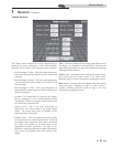
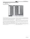
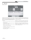
1. Go to the Setup Screen and check all settings. See Section
1 of this manual. Adjust settings if necessary. See Section
1 of this manual for adjustment procedures.
2. Check settings of external limit controls (if any) and
adjust if necessary.
Perform start-up and checks
1. Start boiler and perform checks and tests specified
in Section 9 - Start-up of the SYNC Installation and
Operation Manual.
2. Verify cold fill pressure is correct and that operating
pressure does not go too high.
Check burner flame
1. Inspect flame through observation window.
2. If the flame is unsatisfactory at either high fire or low fire,
turn off boiler and allow boiler to cool down. Remove the
burner and clean it thoroughly using a vacuum cleaner or
compressed air. Do not use compressed air to clean burner
if performed inside a building.
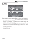
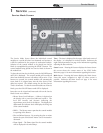
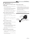
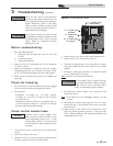
3. Remove the burner, reference FIG. 2-2.
4. When replacing the burner, ensure gasket is in good
condition and positioned correctly (FIG. 2-2).
BURNER
AIR/GAS GASKET
FLAPPER VALVE
BURNER DOOR
BURNER DOOR
HEX NUT (6)
IGNITER
FLAME SENSE
IGNITER GASKET
FLAME SENSE
GASKET
FLAME SENSE
SCREW (2X)
IGNITER SCREW (2X
)
DOOR FIBER
FLAPPER VALVE
SCREW (5X)
Figure 2-2 Burner Assembly
2 Maintenance (continued)
39
Service Manual