


1 Service (continued)
29
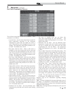
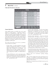
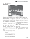
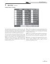
Cascade Screen:
The Cascade Screen provides the status of the cascade system.
Items that can be viewed on the Cascade Screen are as follows:
Boiler Power Level Indicators - For each boiler present in
the cascade a power level indicator will be present above
its corresponding number. The level will rise and
fall indicating the approximate power level of the boiler.
The display box underneath each number will
display “HW” when that boiler is providing heat for a Hot
Water Generation call.
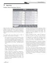
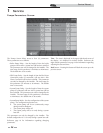
On Timer and Off Timer - The ON and OFF timers are
used to force each boiler in the cascade to have a
minimum on and off time to prevent short cycling.
Block Switch On Timer - Whenever a boiler is
commanded to start, the block switch on timer is started.
This provides a delay between the first ignition system
and the second ignition system inside the boiler. Once the
second ignition system is started, the timer is reset and the
next boiler is prevented from starting until the timer
times out. This process is repeated for each boiler in the
cascade.
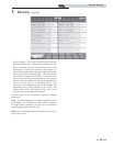
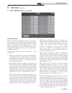
Demand - Shows the status of the cascade. Displayed
items are:
No Demand - the Cascade leader has not received a
system heat call.
SH Demand - the Cascade leader has received a
system heat call.
Set Point Met - the system temperature has met the
User Set Point + the Off Differential.
Pump Delay - the cascade has satisfied a system
heat call and the system pump is running for a fixed
time.
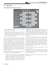
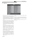
System Temperature - This is the water temperature as measured
by the system sensor located in the system supply piping.
SH Set Point - This is the set point of the cascade system.
The boiler designated as the Leader will use this set point
to determine the power level required to bring the system
temperature to this point. A default value of 50°F (10°C) is
displayed when the SH Call for Heat is inactive.
Time - The time is displayed in the upper right-hand corner of
the display. It is displayed in 24 hour format. Reference the
night setback parameters on page 24 for information regarding
adjusting the date and time.
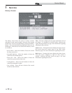
Status button - Pressing this button displays the Status Screen.
This screens shows the current status of the SYNC boiler.
Reference the Status Screen on page 13 for more information
regarding this screen.
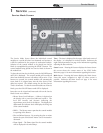
Main button - Pressing this button displays the Main Screen.
From this screen, navigation to eight (8) other screens is
possible. Reference the Main Screen on page 17 for more
information regarding this screen.
Service Manual