


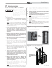

3 Troubleshooting (continued)
49
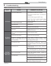
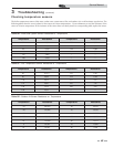
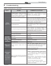
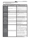
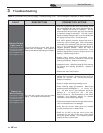
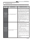
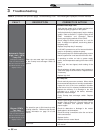
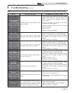
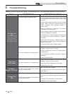
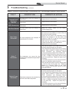
Table 3F (continued from previous page) Troubleshooting Chart - Fault Messages Displayed on Boiler Interface
FAULT DESCRIPTION CORRECTIVE ACTION
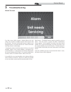
Flame Lost
While Running
(cont’d)
(will require a
manual reset once the
condition has been
corrected. Press the
RESET button on the
display to reset.)
The unit was running and lost the flame
signal. This condition occurred twice .
• If 24 VAC is present at the main control board, check
the wiring between the main control board and the gas
valve. Replace the wiring if necessary. Do not
disconnect the wiring from the gas valve and attempt
to measure voltage at that point. The main control
board can detect if the gas valve is not connected and
will display the Gas Valve / Connection fault.
• If 24 VAC is present, check the outlet of the valve to
ensure the valve is flowing gas. With a manometer
connected to the outlet tap of the gas valve, when the
unit is in the prepurge period, there should be a
negative pressure present. When the valve is
energized a change in pressure should occur. If the
pressure change does not occur, the gas valve is not
opening. Replace the gas valve.
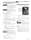
• Inspect flame sensor and associated wiring.
Reference page 39 of this manual for removal and
cleaning procedures. Replace if necessary.
• Inspect the burner. Reference page 39 of this manual
for removal and cleaning procedures. Replace if
necessary.
• Replace the main control board.
Manual Reset
High Limit
(will require a
manual reset once the
condition has been
corrected. Press the
RESET button on the
display to reset.)
The outlet water temperature has exceeded
the setting of the high limit.
• Verify that the system is full of water and that all air
has been properly purged from the system.
• Verify that the boiler is piped properly into the heating
system. Refer to Section 6 - Hydronic Piping of the
SYNC Installation and Operation Manual
for the proper piping methods for the SYNC.
• Check voltage to boiler pump motor on a call for
heat. If voltage is not present, check wiring back to
the pump relay.
• Replace the pump relay if necessary.
• If 120 VAC is present on a call for heat and the boiler
pump is not operating, replace the pump.
• If the system pump is a variable speed pump, ensure
that the system flow is not less than the boiler flow.
• If operating on either an inlet or system supply
sensor, check temperature setting of the main control
board.
• If the high limit has tripped, check setting of the
device.
• Check resistance of water sensors and compare to
Table 3B on page 45 of this manual. Replace sensor
if necessary.
• Replace high limit.
Service Manual