


Page 35
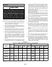
Gas Pressure Adjustment
Gas Flow (Approximate)
1− Operate unit at least 15 minutes before checking gas
flow. Determine the time in seconds for two revolu-
tions of gas through the meter. (Two revolutions as-
sures a more accurate time.) A portable LP gas meter
(17Y44) is available for LP applications.
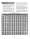
2− Divide the number of seconds by two and compare
to the time in table 11. If manifold pressure is correct
and rate is incorrect, check gas orifices for proper size
and restriction.
3− Remove temporary gas meter if installed.
NOTE− To obtain accurate reading, shut off all other gas
appliances connected to meter.
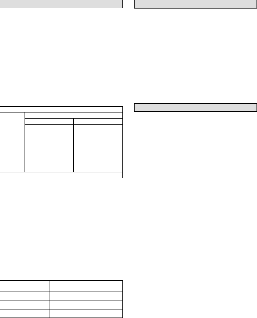
TABLE 11
GAS METER CLOCKING CHART
Unit
Seconds for One Revolution
Unit
Input
Natural LP
Input
Rate
(Btuh)
1 cu ft
Dial
2 cu ft
Dial
1 cu ft
Dial
2 cu ft
Dial
75,000 48 96 120 240
125,000 29 58 72 144
130,000 28 55 69 138
235,000 15 31 38 77
260,000 14 28 35 69
470,000 8 15 19 38
Natural−1000 btu/cu ft LP−2500 btu/cu ft
Note: Table assumes standard temperature (60°F), pressure
(30in.Hg.), and fuel heating values (Btuh/Ft.
3
). Apply pressure
corrections in altitudes above 2000 ft.
Gas Pressure
1 − Check the gas line pressure with the unit (both heat sec-
tions) firing at the high heat input rate. A minimum of 4.5
in. w.c. for natural gas should be maintained.
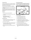
2 − After the line pressure has been checked and ad-
justed, check the high heat regulator pressure on both
gas valves. See figure 20 for gas pressure adjustment
screw location. The low heat setting is factory-set and
is not field-adjustable. The high heat manifold pres-
sure settings are given in table 12.
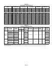
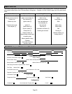
TABLE 12
MANIFOLD GAS PRESSURES (HIGH HEAT)
ALTITUDE
feet (m)
GAS
FUEL
MANIFOLD PRESSURE
in. w.c. (kPa)
0 − 2000 (0 − 610) Natural 3.5 (0.87)
2000 − 4500 (610 − 1372) Natural 3.5 (0.87)
4500 − 7500* (1372 −
2286)
Natural 3.2 (0.80)
*In Canada, certification for installation at altitudes over
4500 feet (1372m) above sea level is the jurisdiction of the
local authorities.
High Altitude Information
In Canada, certification for installation at altitudes over
4500 feet (1372m) above sea level is the jurisdiction of the
local authorities.
See table 12 for the correct high heat manifold pressures to
be maintained for natural gas.
Check the gas line pressure with the unit (both heat sections)
firing at high heat input rate The minimum pressure as
shown on the nameplate for natural gas must be main-
tained.
No orifice change is required. No pressure switch change
is required.
Other Unit Adjustments and Operation
Primary (S10 and S99) Limits
Each heat section has a primary limit located on the heat-
ing compartment vestibule panel. These limits are facto-
ry set and do not require field adjustment.
Flame Rollout Switches (S47 and S69)
Each heat section has a manually reset flame rollout switch.
Each switch is located on the burner top plate. If tripped, a
check for adequate combustion air should be made before
resetting. The switches are non-adjustable.
Combustion Air Pressure Switches (S18 and S45)
Each heat section has a combustion air pressure switch lo-
cated on the heating compartment vestibule panel. Each
switch checks for proper combustion air blower operation
before allowing ignition trial. The switches are factory set
and require no field adjustment.
Blower Motor Controls (K25 Circuit Board),
(K20 Relay), (K123 Relay) and (K36 Relay)
When the gas valves are powered, the blower motor starts
after a delay of 45 seconds. When the gas valves lose pow-
er because the thermostat demand is satisfied, the blower
motor remains running for 150 seconds. These timings are
programmed into the K25 control board and are non-ad-
justable. The board is located in the control box.
If abnormal furnace operation causes either high limit (S10
or S99) to open, the relays K20, K123 and K36 maintain
blower operation until the limit(s) is reset.