


Page 24
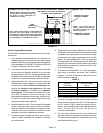
Horizontal Venting
This furnace design is certified by CSA international for
horizontal venting through an outside wall, only with the
use of two Field Controls Company Model SWG-4L side-
wall venting kits, available from any Lennox Dealer Service
Center. No other Field brand venting kits or any other
manufacturer’s venting kits are acceptable. Horizontal
venting of this furnace without the use of the above stated
kits is prohibited.
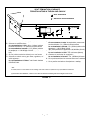
NOTE − Each heat section of the G24−200 unit re-
quires its own sidewall venting kit. The two venting
systems shall be completely separate starting at the
outlet of each heat section and ending with the vent
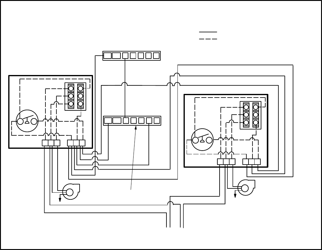
terminal of each Field Controls Venting Kit. (See fig-
ure 12 for field wiring of the two sidewall horizontal
venting kits.)
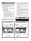
When horizontally vented, the minimum clearance for
terminations from electric meters, gas meters, regula-
tors and relief equipment is 4 ft. (1.2m) for US installa-
tions. Refer to the current CSA−B149.1 for installations in
Canada or with authorities having local jurisdiction.
At vent terminations, care must be taken to maintain pro-
tective coatings over building materials (prolonged expo-
sure to exhaust condensate can destroy protective
coatings). It is recommended that the exhaust outlet not
be located within 6 feet (1.8 m) of a condensing unit be-
cause the condensate can damage the painted coating.
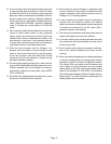
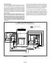
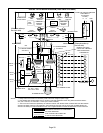
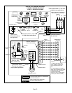
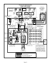
WIRING FOR SIDEWALL VENTING KITS
(Two kits are required − one for each heat section.)
C
L1
L2
120VAC
M
L1 MN
T1 T2 T3
W2 R Y2 G
24 VAC
THERMOSTAT
TERMINAL STRIP FOR THERMOSTAT
CONNECTIONS IN FURNACE JUNCTION BOX
RELAY
CK−43 CONTROL BOX
PRESSURE
SWITCH
SWG
POWER
VENTER
MOTOR
C
FIELD INSTALLED WIRING
FACTORY INSTALLED WIRING
NO
2
1
3
5
4
C
M
L1 MN
T1 T2 T3
RELAY
CK−43 CONTROL BOX
PRESSURE
SWITCH
NO
2
1
3
5
4
SWG
POWER
VENTER
MOTOR
W1 Y1
W2 R Y2 GCW1 Y1
FIGURE 12