


Page 12
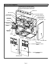
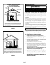
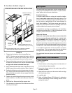
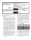
7 − Install the filters and the filter access door.
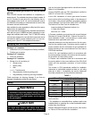
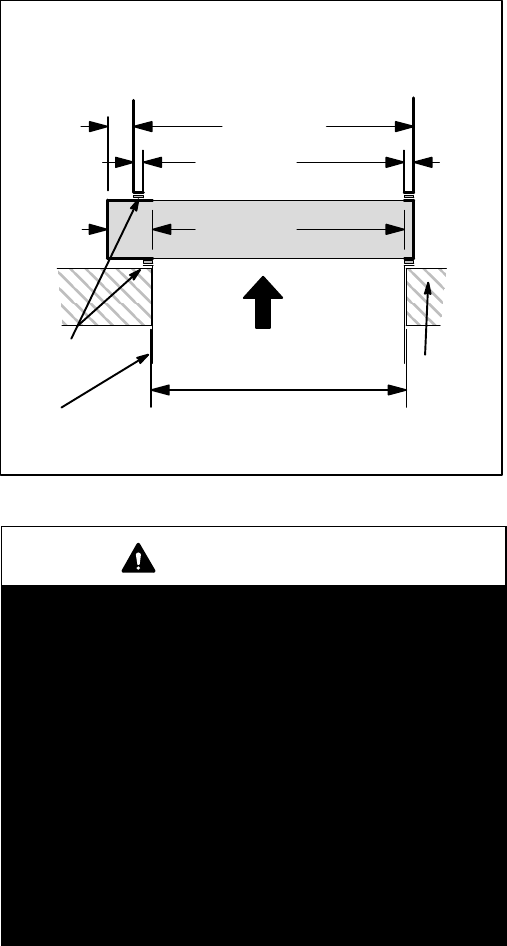
SIDE VIEW
AIR
FLOW
2-3/4
(70)
29-1/4 (743)
27-1/4 (692)
Furnace
Opening
26-1/8 (664) x 50-5/8 (1286)
Floor Opening
1
(25)
1
(25)
26-1/4 (667)
Filter Box
Opening
4-3/4
(121)
BOTTOM RETURN AIR FILTER BOX INSTALLATION
ADHESIVE-
BACKED
FOAM TAPE
UNIT
FILTER
BOX
PLATFORM
RETURN AIR PLENUM
INCHES (mm)
FIGURE 5
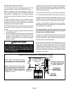
WARNING
Improper installation of the furnace can result in per-
sonal injury or death. Combustion and flue products
must never be allowed to enter the return air system
or the living space. Use screws and joint tape to seal
the return air system to the furnace.
In platform installations with bottom return air, the
furnace should be sealed airtight to the return air ple-
num. A door must never be used as a portion of the
return air duct system. The base must provide a
stable support and an airtight seal to the furnace. Al-
low absolutely no sagging, cracks, gaps, etc.
The return and supply air duct systems must never
be connected to or from other heating devices such
as a fireplace or stove, etc. Fire, explosion, carbon
monoxide poisoning, personal injury and/or proper-
ty damage could result.