


Page 13
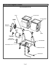
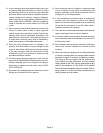
B − Rear Return Air (Refer to figure 6)
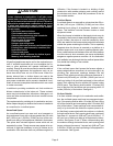
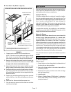
REAR RETURN AIR FILTER BOX INSTALLATION
REPOSITION REAR PANEL WITH FLANGES AS SHOWN.
FOUR FILTERS (Filters may be
also installed through top of frame)
FILTER
ACCESS
PANEL
ADHESIVE-BACKED
FOAM TAPE
(Apply to filter box)
(Seal air-tight with adhesive-backed foam tape.)
UNIT
RETURN AIR
FILTER BOX
FILTER
ACCESS
PANEL
FIGURE 6
1 − Determine the location of the furnace/filter box.
NOTE − Filter box can be installed with right or left side
filter access or top-rear filter access. Allow enough
room when positioning the furnace for filter access.
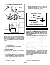
2 − Remove the bottom-rear panel from the furnace and
re-install on the bottom of the furnace as shown. Seal
air-tight with adhesive-backed foam tape.
3 − Apply adhesive-backed foam tape to the filter box (side
facing furnace) all around the opening. Refer to figure 6.
4 − Position the filter box over the furnace return air open-
ing. The top of the filter box should be in the up" posi-
tion and the filter box and the furnace edges flush at the
sides and bottom.
5 − Fasten using self-drilling self-tapping screws provided
with the filter box. Use the frame clearance holes as a
guide.
6 − Install the four filters and the filter access door.
7 − Size the return air plenum to fit the filter box and then
seal the joint air tight.
Duct System
Size and install supply and return air duct system using in-
dustry-approved standards that result in a quiet and low-
static system with uniform air distribution.
Supply Air Plenum
Furnaces installed without a cooling coil require the installa-
tion of a removable access panel in the supply air duct. The
access panel should be large enough to permit inspection (ei-
ther by smoke or reflected light) of the heat exchanger for
leaks after installation. The furnace access panel must al-
ways be in place when the furnace is operating and it must
not allow leaks into the supply air duct system.
In applications requiring air conditioning, see installation
instructions provided with C17-090/120 evaporator coil for
supply air plenum size and connection.
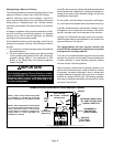
Return Air Plenum
Return air must not be drawn from a room where this
furnace, or any other gas appliance (i.e., a water heat-
er), is installed. When return air is drawn from a room, a
negative pressure is created in the room. If a gas ap-
pliance is operating in a room with negative pressure, the
flue products can be pulled back down the vent pipe and
into the room. This reverse flow of the flue gas may result
in incomplete combustion and the formation of carbon
monoxide gas. This toxic gas might then be distributed
throughout the house by the furnace duct system.
Size and install return air plenum as indicated in previous
section.
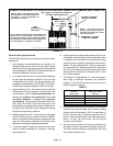
Blower Motor / Drive Installation
A − Motor Installation
Refer to figure 7.
1 − Check the box on the rating plate to indicate which of
the drive kits are being installed.
2 − Secure the blower motor to the motor base with the
hardware provided.
3 − Slide the motor pulley onto the motor shaft and align
with the blower pulley.
4 − Install the belt.
5 − Refer to Setting Blower CFM Section" to determine
blower RPM setting and the following section for ad-
justing belt tension.