


Page 21
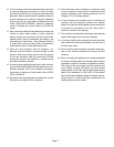
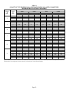
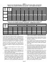
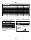
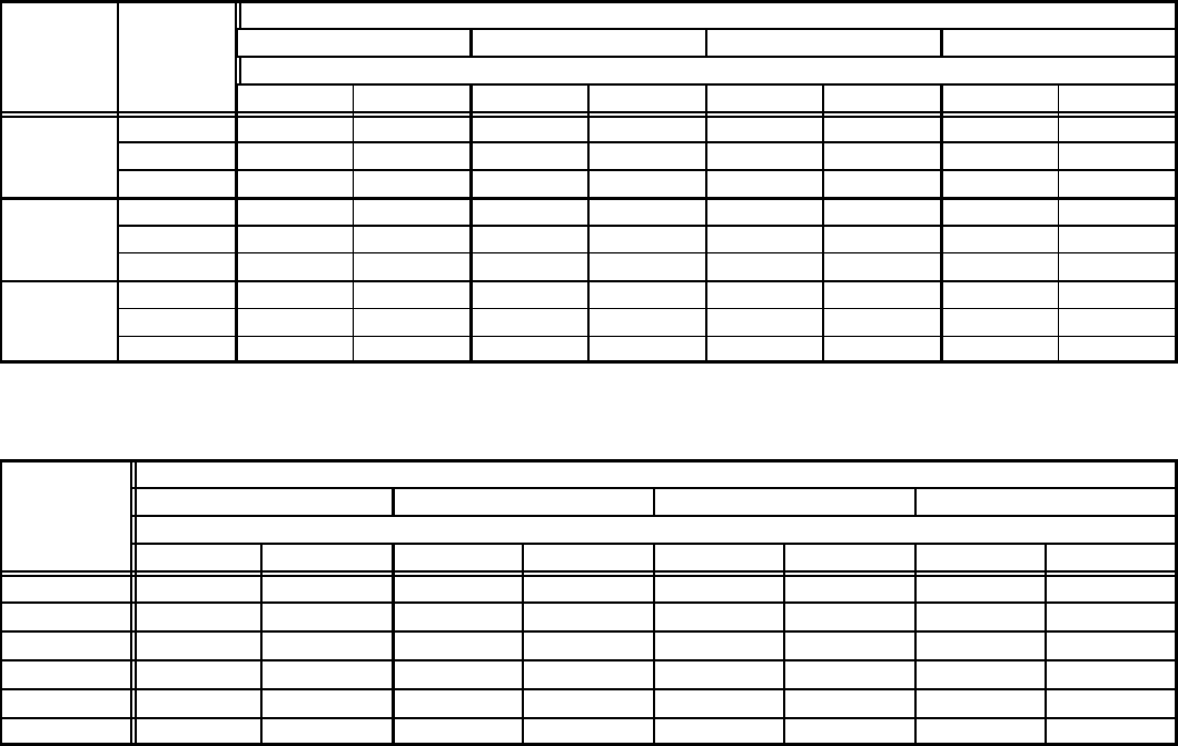
TABLE 7
CAPACITY OF TYPE B DOUBLE-WALL VENT WITH SINGLE-WALL METAL CONNECTORS
SERVING TWO OR MORE CATEGORY I APPLIANCES − VENT CONNECTOR CAPACITY
Vent
Connector
Vent and Connector Diameter − D (inches)
V
ent
Hei
g
ht
C
onnector
Rise
4 Inch 5 Inch 6 Inch 7 Inch
Height
H
(feet)
Rise
R
(feet)
Appliance Input Rating in Thousands of Btu Per Hour
(feet) (feet)
MIN MAX MIN MAX MIN MAX MIN MAX
1 NR NR NR NR NR NR 207 223
6
2 NR NR NR NR 168 182 215 251
6
3 NR NR 121 131 174 198 222 273
1 79 87 116 138 177 214 238 291
15
2 83 94 121 150 185 230 246 314
3 87 100 127 160 193 243 255 333
1 77 110 113 175 169 278 226 380
30
2 81 115 117 185 177 290 236 397
3 85 119 122 193 185 300 244 412
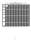
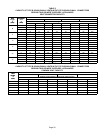
TABLE 8
CAPACITY OF TYPE B DOUBLE-WALL VENTS WITH SINGLE-WALL METAL CONNECTORS
SERVING TWO OR MORE CATEGORY I APPLIANCES − COMMON VENT CAPACITY
Vent
Common Vent Diameter − D (inches)
V
ent
Hei
g
ht
4 Inch 5 Inch 6 Inch 7 Inch
Height
H
(feet)
Appliance Input Rating in Thousands of Btu Per Hour
(feet)
FAN + FAN FAN + NAT FAN + FAN FAN + NAT FAN + FAN FAN + NAT FAN + FAN FAN + NAT
6 89 78 136 113 200 158 304 244
8 98 87 151 126 218 173 331 269
10 106 94 163 137 237 189 357 292
15 121 108 189 159 275 221 416 343
20 131 118 208 177 305 247 463 383
30 145 132 236 202 350 286 533 446
Removal of the Furnace from Common Vent
In the event that an existing furnace is removed from a
venting system commonly run with separate gas ap-
pliances, the venting system is likely to be too large to prop-
erly vent the remaining attached appliances. The following
test should be conducted while each appliance in operation
and the other appliances not in operation remain con-
nected to the common venting system. If the venting sys-
tem has been installed improperly, the system must be
corrected as indicated in the general venting requirements
section.
1 − Seal any unused openings in the common venting
system.
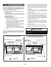
2 − Visually inspect the venting system for proper size and
horizontal pitch. Determine there is no blockage or re-
striction, leakage, corrosion, or other deficiencies which
could cause an unsafe condition.
3 − To the extent that it is practical, close all building doors
and windows and all doors between the space in which
the appliances remaining connected to the common
venting system are located and other spaces of the build-
ing. Turn on clothes dryers and any appliances not con-
nected to the common venting system. Turn on any
exhaust fans, such as range hoods and bathroom ex-
hausts, so they will operate at maximum speed. Do not
operate a summer exhaust fan. Close fireplace dampers.
4 − Follow the lighting instructions. Place the appliance being
inspected in operation. Adjust thermostat so appliance
will operate continuously.
5 − Test for spillage of the flue gases at the draft hood relief
opening after 5 minutes of main burner operation. Use
the flame of a match or candle, or smoke from a cigarette,
cigar or pipe.
6 − After determining that each appliance remaining con-
nected to the common venting system properly vents
when tested as indicated instep 3, return doors, windows,
exhaust fans, fireplace dampers and any other gas−burn-
ing appliance to their previous condition of use.
7 − If improper venting is observed during any of the
above tests, the common venting system must be cor-
rected. The common venting system should be re-
sized to approach the minimum size as determined by
using the appropriate tables in appendix G in the cur-
rent standards of the National Fuel Gas Code ANSI
Z223.1 /NFPA54 in the USA, and the appropriate
Category 1 Natural Gas appliances venting sizing
tables in the current standards of the CSA−B149.1
Natural Gas Installation Code in Canada.