


Page 11
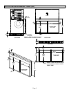
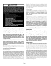
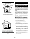
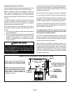
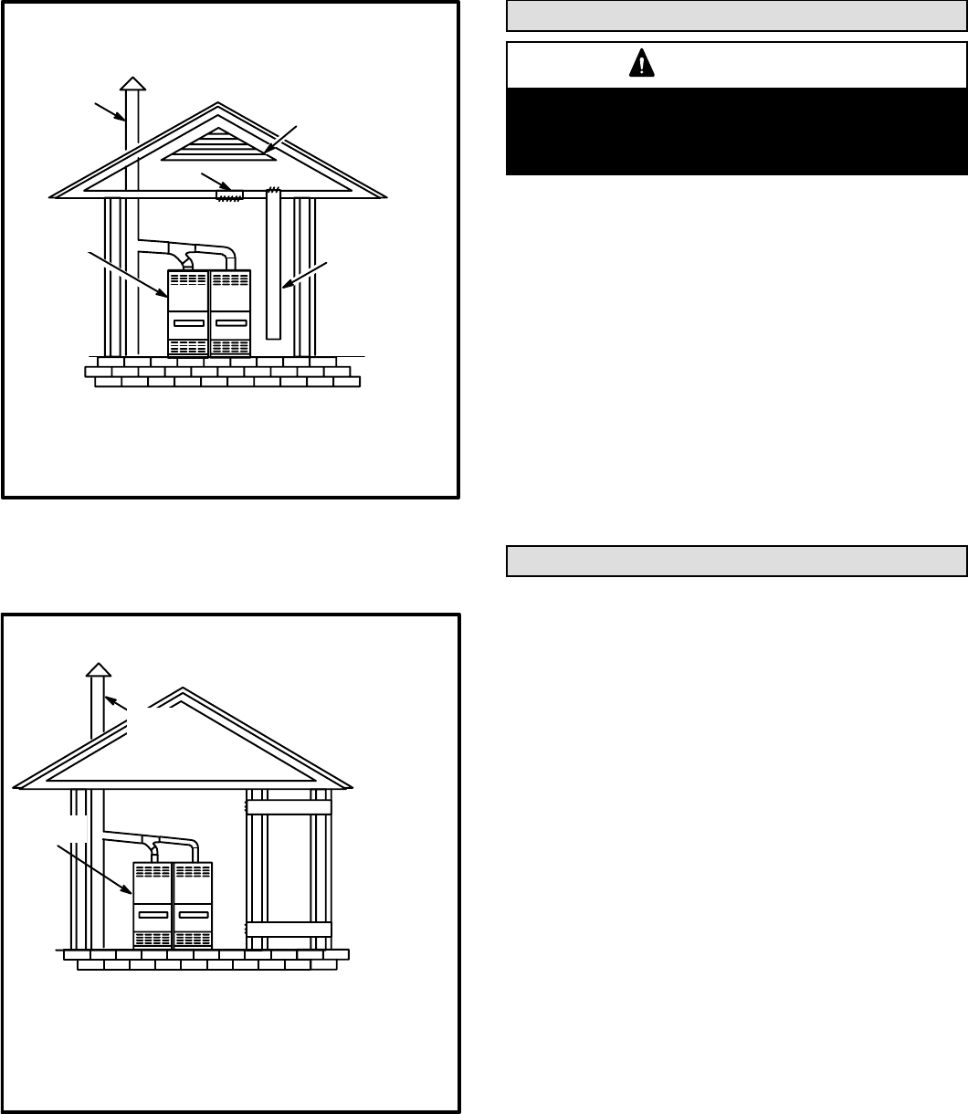
EQUIPMENT IN CONFINED SPACE
ALL AIR FROM OUTSIDE
(All Air Through Ventilated Attic)
CHIMNEY
OR GAS
VENT
OUTLET
AIR
VENTILATION LOUVERS
(Each end of attic)
INLET AIR
(Ends 12 in.
above bottom)
G24−200
FURNACE
NOTE−The inlet and outlet air openings shall each have a
free area of at least one square inch (645 mm
2
) per 4,000
Btu (1.17 kW) per hour of the total input rating of all equip-
ment in the enclosure.
FIGURE 3
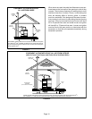
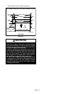
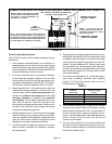
EQUIPMENT IN CONFINED SPACE
(ALL AIR FROM OUTSIDE)
OUTLET AIR
INLET AIR
CHIMNEY
OR GAS
VENT
G24−200
FURNACE
NOTE−Each air duct opening shall have a free area of at least
one square inch (645 mm
2
) per 2,000 Btu (.59 kW) per hour of
the total input rating of all equipment in the enclosure. If the
equipment room is located against an outside wall and the air
openings communicate directly with the outdoors, each open-
ing shall have a free area of at least one square inch (645 mm
2
)
per 4,000 Btu (1.17 kW) per hour of the total input rating of all
other equipment in the enclosure.
FIGURE 4
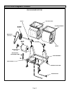
Setting Equipment
WARNING
Do not install the furnace on its front or its back. Do-
ing so will adversely affect the operation of the safety
control devices, which could result in personal inju-
ry or death.
The Lennox G24−200 upflow gas furnace can be
installed with rear or bottom return air. If unit is installed
on a platform with bottom return air, furnace/filter box must
be sealed airtight at the platform to ensure proper and safe
operation.
Select a location that allows for required clearances listed
on unit rating plate. Also consider gas supply connections,
electrical supply, vent connection, installation and service
clearances [24 inches (610mm) at unit front] and filter ac-
cessibility.
The furnace must be leveled using shims or leveling bolts
(field provided). The corner gussets provided in the furnace
base will accept leveling bolts.
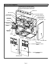
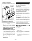
Return Air Plenum / Filter Box Installation
Return air openings are provided at rear and in bottom of
unit. A return air closure panel is shipped secured to the
rear opening.
A − Bottom Return Air (Refer to figure 5)
1 − Determine the location of the furnace/filter box.
2 − Cut 50-5/8 x 26-1/8 (128.6cm x 66.4cm) opening in the
return air platform.
3 − Fabricate the return air plenum with right angle flanges
and insert into the floor opening.
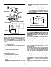
4 − Remove filter box access door and filters.
5 − Apply adhesive-backed foam tape to the bottom of the
filter box all around the opening. Position the filter box
over the return air plenum. Fasten as required using
self-tapping screws provided.
Make sure there is an air tight seal between the
platform/return air plenum and filter box.
6 − Apply adhesive-backed foam to the top of the filter box
all around the opening. Place furnace over the filter box
with sides and rear of furnace and filter box flush. Fas-
ten as required.
Make sure there is an air tight seal between the fur-
nace and the filter box.