


Page 18
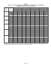
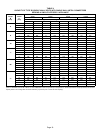
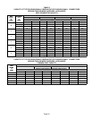
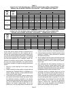
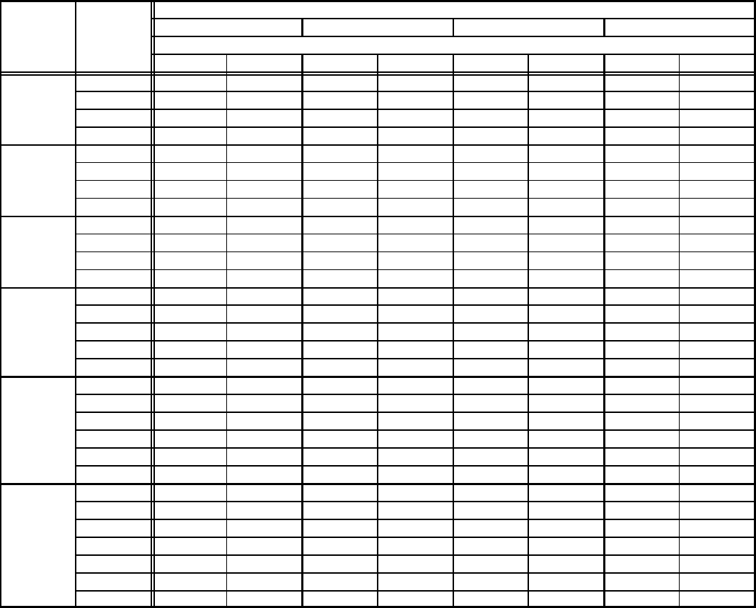
TABLE 3
CAPACITY OF TYPE B DOUBLE-WALL VENTS WITH TYPE B DOUBLE-WALL CONNECTORS
SERVING A SINGLE CATEGORY I APPLIANCE
Vent and Connector Diameter − D (inches)
Height
H
Lateral
L
3 Inch 4 Inch 5 Inch 6 Inch
H
(
feet
)
L
(
feet
)
Appliance Input Rating in Thousands of Btu Per Hour
(feet)
(feet)
MIN MAX MIN MAX MIN MAX MIN MAX
0 0 78 0 152 0 251 0 375
6
2 13 51 18 97 27 157 32 232
6
4 21 49 30 94 39 153 50 227
6 25 46 36 91 47 149 59 223
0 0 84 0 165 0 276 0 415
8
2 12 57 16 109 25 178 28 263
8
5 23 53 32 103 42 171 53 255
8 28 49 39 98 51 164 64 247
0 0 88 0 175 0 295 0 447
10
2 12 61 17 118 23 194 26 289
10
5 23 57 32 113 41 187 52 280
10 30 51 41 104 54 176 67 267
0 0 94 0 191 0 327 0 502
2 11 69 15 136 20 226 22 339
15
5 22 65 30 130 39 219 49 330
10 29 59 40 121 51 206 64 315
15 35 53 48 112 61 195 76 301
0 0 97 0 202 0 349 0 540
2 10 75 14 149 18 250 20 377
20
5 21 71 29 143 38 242 47 367
20
10 28 64 38 133 50 229 62 351
15 34 58 46 124 59 217 73 337
20 48 52 55 116 69 206 84 322
0 0 100 0 213 0 374 0 587
2 9 81 13 166 14 283 18 432
5 21 77 28 160 36 275 45 421
30
10 27 70 37 150 48 262 59 405
15 33 64 44 141 57 249 70 389
20 56 58 53 132 66 237 80 374
30 NR NR 73 113 88 214 104 346
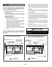
NOTE − Single appliance venting configurations with zero lateral lengths are assumed to have no elbows in the vent system. For all other vent configurations, the vent
system is assumed to have two 90_ elbows. For each additional 90_ elbow or equivalent (for example two 45_ elbows equal one 90_ elbow) beyond two, the maximum
capacity listed in the venting table should be reduced by 10 percent (0.90 x maximum listed capacity).