


Page 25
Gas Piping
NOTE − The flexible connector supplied with the unit
must not be modified and must be installed between
the two combination gas controls.
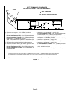
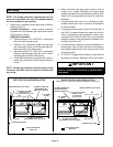
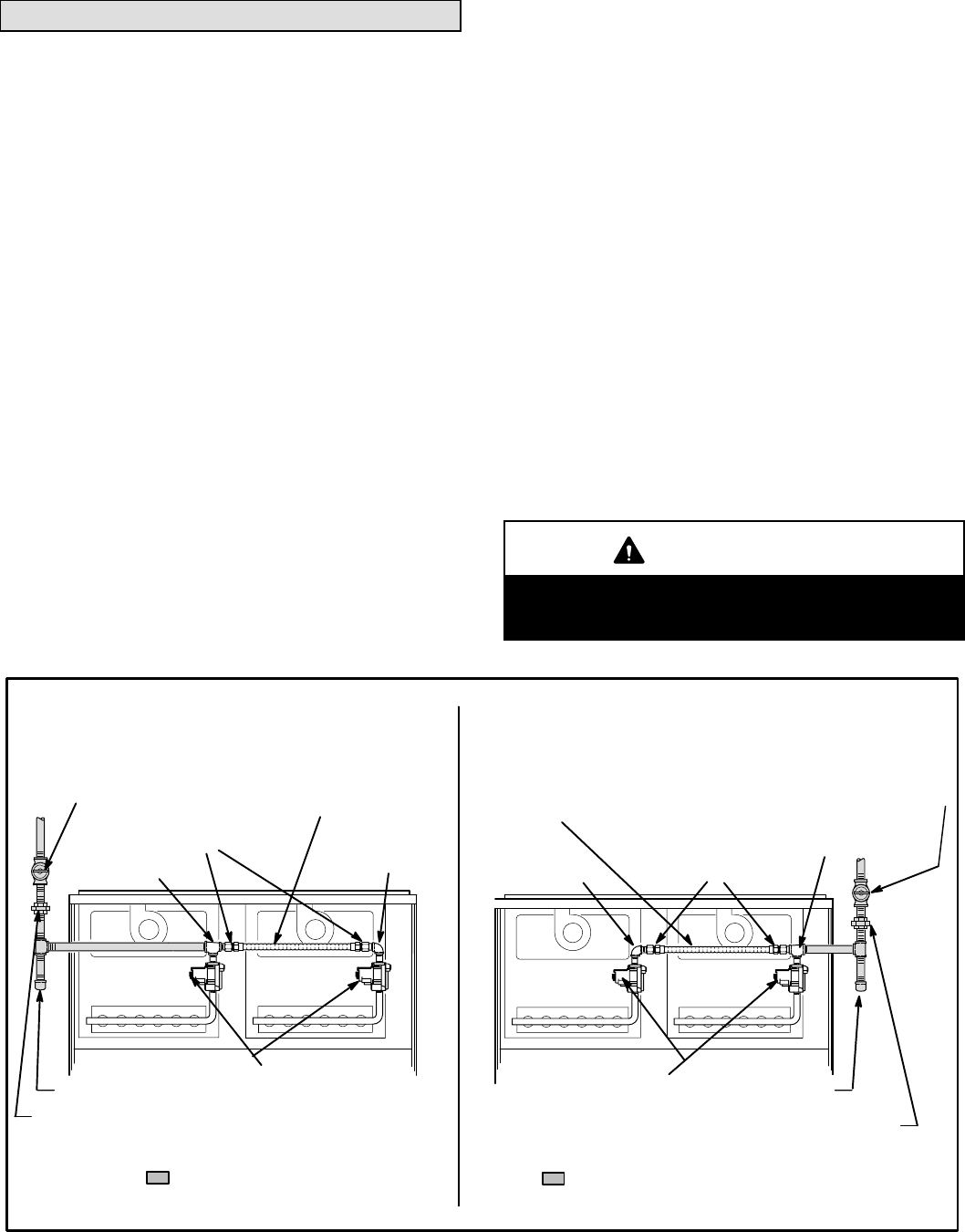
1 − Piping can be installed to enter either side of cabinet.
Refer to figure 13.
Left-Side Installation − Install flexible connector
(supplied with unit) between gas valves and connect
supply piping as shown.
Right-Side Installation −
a − Remove tee and 1/2 in. NPTx1/2 in. male brass
fitting from left side gas valve.
b − Remove 1/2 in. elbow and nipple from right side
gas valve and re-install on left side gas valve fac-
ing toward right side cabinet entry.
c − Re-install tee and 1/2 in. NPTx1/2 in. male brass
fitting on right side gas valve with 3/4 in. side of
tee facing the right side cabinet entry.
d − Install flexible connector (supplied with unit) be-
tween gas valves and connect supply piping as
shown.
NOTE − Flexible gas connector must be routed so that
connector does NOT come in contact or interfere with
any wiring.
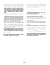
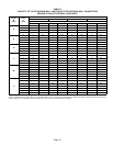
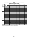
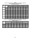
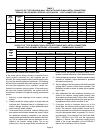
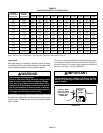
2 − When connecting the gas supply, factors such as
length of run, number of fittings and furnace rating
must be considered to avoid excessive pressure drop.
Table 9 lists recommended pipe sizes for typical ap-
plications.
3 − The gas piping must not run in or through air ducts,
clothes chutes, gas vents or chimneys, dumbwaiters
or elevator shafts.
4 − The piping should be sloped 1/4 inch (6.4 mm) per 15
feet (4.57 m) upward toward the meter from the fur-
nace. The piping must be supported at proper inter-
vals [every 8 to 10 feet (2.44 to 3.01 m) using suitable
hangers or straps. A drip leg should be installed in ver-
tical pipe runs to the unit.
5 − In some localities, codes may require installation of a
manual main shut-off valve and union (furnished by
the installer) external to the unit. Union must be of the
ground joint type.
6 − A 1/8" N.P.T. plugged tap is located on gas valve for
test gauge connection. See figure 20 for tap location.
IMPORTANT
Compounds used on threaded joints of gas piping
must be resistant to the actions of liquified petro-
leum gases.
GROUND JOINT UNION
DRIP LEG
RIGHT SIDE GAS LINE INSTALLATION
FIELD PROVIDED AND
INSTALLED
FLEXIBLE CONNECTOR
SHIPPED WITH UNIT
AND FIELD INSTALLED
MANUAL MAIN SHUT-OFF VALVE
AUTOMATIC GAS VALVE
(WITH MANUAL SHUT-OFF VALVE)
LEFT SIDE GAS LINE INSTALLATION
FLEXIBLE CONNECTOR
SHIPPED WITH UNIT
AND FIELD INSTALLED
MANUAL MAIN SHUT-OFF VALVE
1/2 in. STREET
ELBOW
TEE
(3/4 in. X 1/2 in. X 1/2 in.)
1/2 in. NPT X 1/2 in. MALE
BRASS FITTING
(Provided with flex connector)
AUTOMATIC GAS VALVE
(WITH MANUAL SHUT-OFF VALVE)
GROUND JOINT UNION
DRIP LEG
(See item # 1 on previous page for installation instructions)
FIELD PROVIDED AND
INSTALLED
1/2 in. STREET
ELBOW
TEE
(3/4 in. X 1/2 in. X 1/2in. )
1/2 in. NPT X 1/2 in. MALE
BRASS FITTING
(Provided with
flex connector)
FIGURE 13