


Page 23
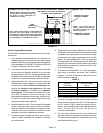
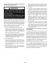
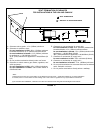
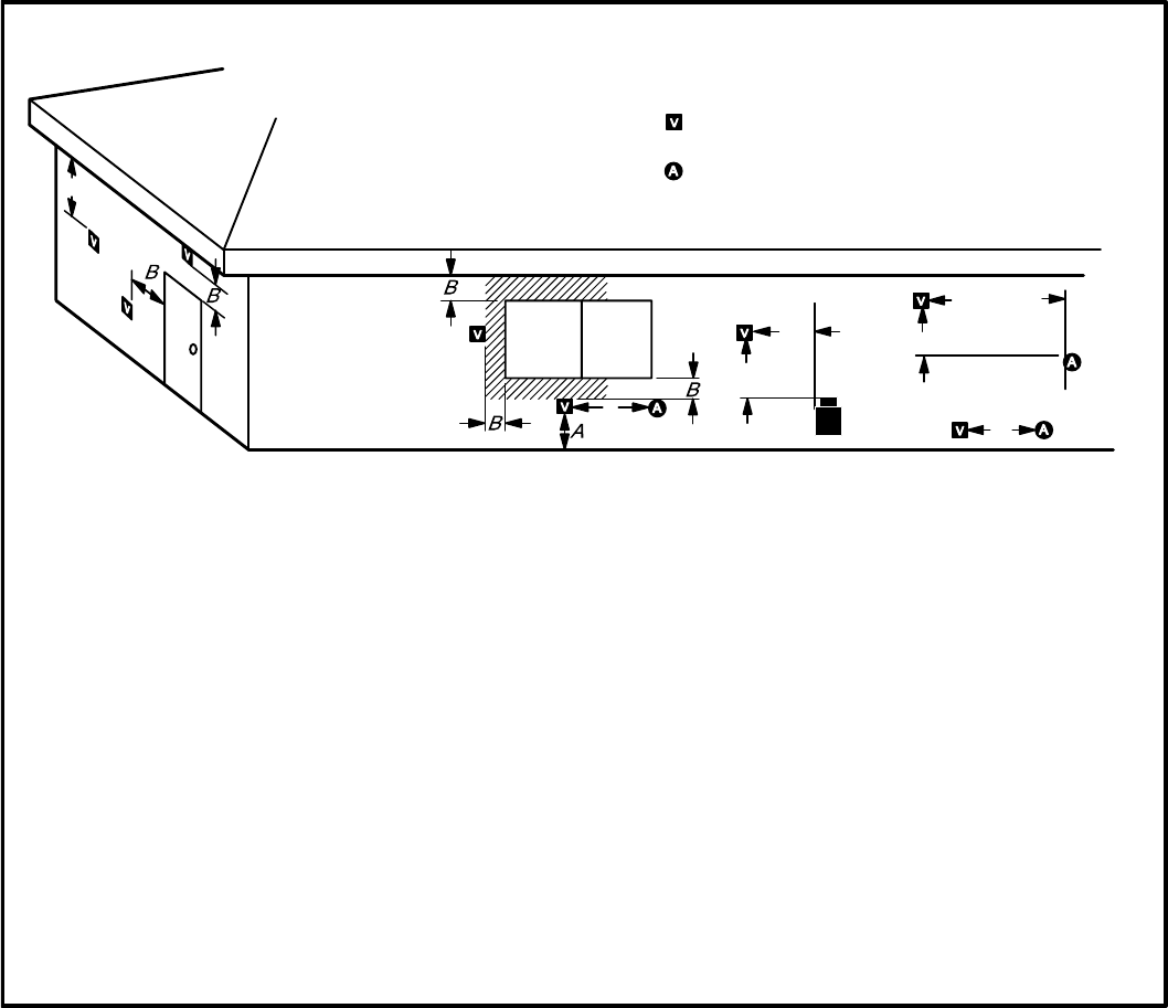
FIGURE 11
VENT TERMINATION CLEARANCES
FOR INSTALLATIONS IN THE USA AND CANADA*
A − Clearance above grade − 12 in. (305mm) minimum.
B − Clearance to window or door −
for vent installations in USA − 48 in. (1219mm) minimum
horizontal and below, 12 in. (305mm) minimum above.
for vent installations in Canada − 12 in. (305mm) minimum
for appliances 100,000 Btuh (30 kW);
36 in. (0.9m) minimum for appliances > 100,000 Btuh (30
kW).
C − Do not position terminations directly under roof eaves.
D − Clearance to electric meters, gas meters, regulators, and
relief equipment −
for vent installations in USA − 48 in (1219mm) minimum.
for vent installations in Canada − see current edition of
CSA B149 Code.
E − Clearance to non−mechanical air supply inlet
for vent installations in USA − 48 in. (1219mm) minimum hor-
izontal and below, 12 in. (305mm) minimum above.
for vent installations in Canada − 12 in. (305mm) minimum for
appliances 100,000 Btuh (30 kW);
36 in. (0.9m) minimum for appliances > 100,000 Btuh (30 kW).
F − Clearance to mechanical air supply inlet −−
for vent installations in USA − 36 in. minimum (914mm).
G − Clearance to mechanical air supply inlet −−
for vent installations in Canada − 72 in. (1829mm) minimum.
H − Do not point terminations into recessed areas such as window
wells, stairwells or alcoves.
J − Do not position terminations directly above a walkway.
* Note −
(I) Dimensions are from the current edition of The National Fuel Gas Code − ANSI-Z223.1/NFPA 54 for USA installations.
In Canada, refer to current edition of CSA building code. Local codes or regulations may require different clearances.
less than
10 ft (3.048M)
C
D
D
E
F
G
(II) In Non-Direct Vent installations, combustion air is taken from indoors and the flue gases are discharged to the outdoors.
− VENT TERMINATION
− AIR INLET OF OTHER APPLIANCE