


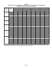
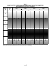
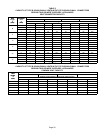
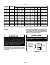
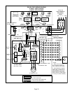
Page 26
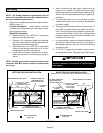
TABLE 9
GAS PIPE CAPACITY − FT
3
/HR (KL/HR)
Nominal Internal
Length of Pipe - Feet (m)
Nominal
Iron Pipe Size
Inches(mm)
Internal
Diameter
Inches(mm)
10
(3.048)
20
(6.096)
30
(9.144)
40
(12.192)
50
(15.240)
60
(18.288)
70
(21.336)
80
(24.384)
90
(27.432)
100
(30.480)
1/4
(6.35)
.364
(9.246)
43
(1.13)
29
(.82)
24
(.68)
20
(.57)
18
(.51)
16
(.45)
15
(.42)
14
(.40)
13
(.37)
12
(.34)
3/8
(9.53)
.493
(12.522)
95
(2.69)
65
(1.84)
52
(1.47)
45
(1.27)
40
(1.13)
36
(1.02)
33
(.73)
31
(.88)
29
(.82)
27
(.76)
1/2
(12.7)
.622
(17.799)
175
(4.96)
120
(3.40)
97
(2.75)
82
(2.32)
73
(2.07)
66
(1.87)
61
(1.73)
57
(1.61)
53
(1.50)
50
(1.42)
3/4
(19.05)
.824
(20.930)
360
(10.19)
250
(7.08)
200
(5.66)
170
(4.81)
151
(4.28)
138
(3.91)
125
(3.54)
118
(3.34)
110
(3.11)
103
(2.92)
1
(25.4)
1.049
(26.645)
680
(919.25)
465
(13.17)
375
(10.62)
320
(9.06)
285
(8.07)
260
(7.36)
240
(6.80)
220
(6.23)
205
(5.80)
195
(5.52)
1−1/4
(31.75)
1.380
(35.052)
1400
(39.64)
950
(26.90)
770
(21.80)
660
(18.69)
580
(16.42)
530
(15.01)
490
(13.87)
460
(13.03)
430
(12.18)
400
(11.33)
1−1/2
(38.1)
1.610
(40.894)
2100
(59.46)
460
(41.34)
1180
(33.41)
990
(28.03)
900
(25.48)
810
(22.94)
750
(21.24)
690
(19.54)
650
(18.41)
620
(17.56)
2
(50.8)
2.067
(52.502)
3950
(111.85)
2750
(77.87)
2200
(62.30)
1900
(53.80)
1680
(47.57)
1520
(43.04)
1400
(39.64)
1300
(36.81)
1220
(34.55)
1150
(32.56)
2−1/2
(63.5)
2.469
(67.713)
6300
(178.39)
4350
(123.17)
3520
(99.67)
3000
(84.95)
2650
(75.04)
2400
(67.96)
2250
(63.71)
2050
(58.05)
1950
(55.22)
1850
(52.38)
3
(76.2)
3.068
(77.927)
11000
(311.48)
7700
(218.03)
6250
(176.98)
5300
(150.07)
4750
(134.50)
4300
(121.76)
3900
(110.43)
3700
(104.77)
3450
(97.69)
3250
(92.03)
4
(101.6)
4.026
(102.260)
23000
(651.27)
15800
(447.39)
12800
(362.44)
10900
(308.64)
9700
(274.67)
8800
(249.18)
8100
(229.36)
7500
(212.37)
7200
(203.88)
6700
(189.72)
NOTE − Capacity given in cubic feet (m
3
) of gas per hour and based on 0.60 specific gravity gas.
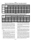
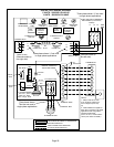
Leak Check
After gas piping is completed, carefully check all piping
connections (factory- and field-installed) for gas leaks. Use
a leak detecting solution or other preferred means.
WARNING
FIRE OR EXPLOSION HAZARD
Failure to follow the safety warnings exactly could
result in serious injury, death or property damage.
Never test for gas leaks with an open flame. Use a
commercially available soap solution made specifi-
cally for the detection of leaks to check all connec-
tions. A fire or explosion may result causing proper-
ty damage, personal injury or loss of life.
NOTE − In case emergency shutdown is required, shut off
the main manual gas valve and disconnect the main power
to the furnace. These devices should be properly labeled
by the installer.
The furnace must be isolated from the gas supply system
by closing its individual manual shut-off valve during any
pressure testing of the gas supply system at pressures
equal to or less than 1/2 psig (3.48 kPa).
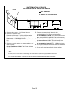
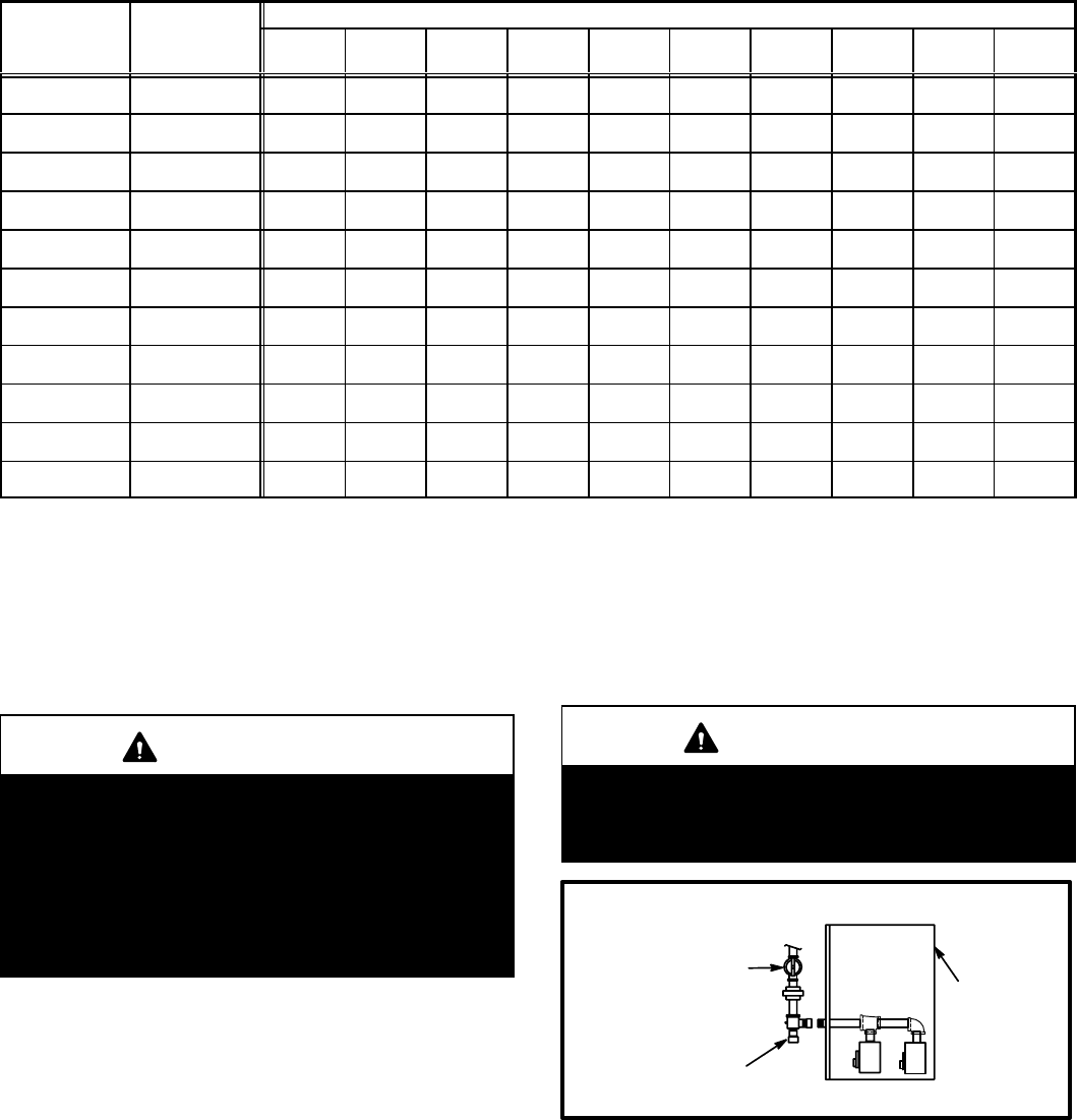
IMPORTANT
When testing pressure of gas lines, gas valve must
be disconnected and isolated. See figure 14. Gas
valves can be damaged if subjected to more than 1/2
psig (3.48 kPa).
MANUAL MAIN
SHUT−OFF VALVE
WILL NOT HOLD
NORMAL TEST
PRESSURE
CAP
ISOLATE
GAS
VALVES
FURNACE
FIGURE 14