


Multi-Media Unit: Installation Instructions
5–10
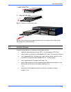
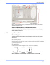
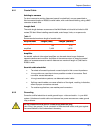
Fig. 48. FAULT RELAY connector on Multi-Media unit’s back-panel, showing
connection to an external alarm panel.
Do not connect a device to CONTROL output 6 after enabling the FAULT RELAY.
Enabling the FAULT RELAY provides a status pulse at CONTROL 6, disabling it as a
general-purpose output. Connecting a device to CONTROL 6 could interfere with the
relay’s performance.
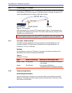
5.9 Point of Sale Hardware
Cable
For a point-of-sale (POS) device or other data communication equipment (DCE), use a
standard RS-232 cable with a female DB-9 connector.
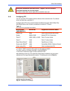
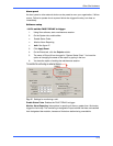
5.9.1 Configuring POS
For procedures on using the Data Recording tab in the Maintenance dialog, to configure
POS devices, consult the Admin User Guide for Rapid Eye Multi-Media units.
5.10 External Modems
At unit, connected to a network
You can connect an external modem to a LAN-based Multi-Media unit.
• for POTS. Honeywell recommends a U.S. Robotics Sportster, transmitting at a
least 33.6Kps, for POTS connections.
• for ISDN. A U.S. Robotics Courier I-Modem is recommended for ISDN
connections. Please refer to your modem manufacturer's documentation for the
modem’s configuration.
For use of an external modem with a POTS-based Multi-Media unit, contact
Honeywell Video Systems technical support, at: 1 (800) 796–2288; i.e., 1 (800)
796–CCTV.