


Multi-Media Unit: Installation Instructions
5–8
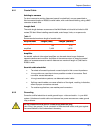
Table 14
Sensor hardware
Acronym Sensor Input Implication
NO Normally Open input is active when switch goes ON
NC Normally Closed input is active when switch goes OFF
EOL End of Line input is active when switch goes ON, or if
wires to the alarm sensor are cut
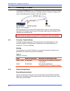
5.7 Control Outputs
Purpose
A View operator can activate outputs.
Up to 24 mA can be drawn at each output.
Cable
Use hookup wire in the 20-gauge range to connect the outputs to relay triggered devices
(locks, gates, warning sirens and so on) to a Multi-Media unit.
Tools
You may need:
• a slot screwdriver—supplied. The screws are slightly smaller than those for a
1/8" screwdriver.
• a wire stripper.
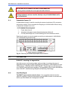
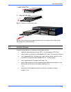
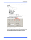
Connector
1. From the hookup wires’ tips, strip approximately 0.6 cm (1/4 inch) of insulation.
2. Insert each relay control wire to the screw-type, terminal connector on the
CONTROL OUTPUTS terminal strip: one wire to ground and the other wire to
the numbered connection you choose.
To avoid short-circuits, ensure that bare wire is not visible at the rear panel.
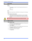
5.8 System Monitoring
Fault relay
A Multi-Media unit can be monitored for failure:
• to function
• to report alarms
Should such a failure last more than 19 minutes, the FAULT RELAY is triggered.