


Page 62 IFS-2600 Installation & Programming Manual
P/N 10069 ECN08-0066
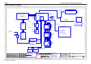
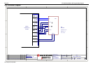
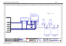
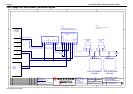
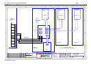
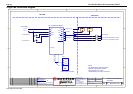
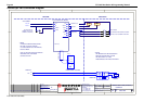
Single Fan Connection Diagram
1
1
2
2
3
3
4
4
D D
C C
B B
A A
Rev
Size
Drg.
No.
Title
Sheet:
Drawn/
Traced
Engineer
Design
Approved
This Drawing must notbeused for Construction
unlesssigned as approved
7 Columbia Court,
Norwest Business Park
Baulkham Hills NSW 2153
AUSTRALIA
Tel
Fax
Email: support@inertia.com.au
A4
No.
Revision -revise on CAD. Do not amend byhand Eng. App. Date
Copyright
This document is&shall
remainthepropertyof
NotifierInertia FireSystems
Unauthorised useof this
documentin anyway is
prohibited.
Drawing FileNo.
C
O
61 2 9894 1444
61 2 9899 4156
=DocumentFullPathAndName
Of:
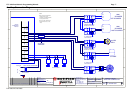
OFF
AUTO
ON
RUN
STOP
FAULT
+24
0V
START1
STOP1
CONTROL
PCB1128
+24
START
STOP
RUN
STOP
FLT
INDICATION
FAN 1
COMMON +VE
FRONT PANEL CONTROL
FIRE PANEL
FIELDWIRING
START STOP
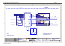
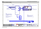
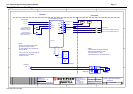
* NOTE
THE MECHANICAL SERVICES BOARD
MUST BE CONFIGURED TO HAVE
THE STOP RELAY TO TAKE
PRECEDENCE OVER THE START RELAY
19/8/05 I PERRY
A
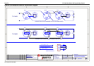
SINGLE FAN (GENERAL)
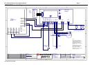
2600-DUAL FAN
FAN TERMINATION BOARD
AUX +24
AUX 0V
AUX POWER
CONTROL
FAN RUNNING
FAN STOPPED AND POWER AVAILABLE
FAN FAULT OR NO POWER AVAILABLE
FAN START RELAY
FAN STOP RELAY
RIBBON CABLE
1 1