


IFS-2600 Installation & Programming Manual Page 11
P/N 10069 ECN08-0066
TECHNICAL DESCRIPTION
GENERAL
The IFS-2600 in its most basic form comprises of three boards, the main control board, the main termination
board and the power supply board.
The main control board contains the Microprocessor, EPROM, RAM and E
2
ROM. The main control board also
has the liquid crystal display and keypad attached. All of the "delicate" electronics have been placed on this
board. The main control board complete with the inner door is easily removed during installation to avoid
damage and allow greater access to the field terminals.
The main termination board contains the one power supply for 5V logic, and connectors for a Power Supply
and Battery Charger daughter board, the first eight zones, all common outputs and the printer interface. All
charger settings, fuses etc are located on this board. The Power Supply and Battery Charger board contains
two switch mode regulators, 26.5V for the panel power, 27.3V for the battery charger.
Up to seven (7) zone expansion boards can be added to the system to increase its detection capability. These
boards contain the same electronics as on the main termination board for zone scanning. Addressing is by a
jumper that selects which group of eight zones the board refers to.
Up to four (4) zone indicator boards can also be added. These boards will display the status of the zone
expansion boards fitted.
Up to eight (8) relay boards can be added. These boards contain 8 change-over relay contacts, each rated at
1 amp. These boards require no addressing, as they work on a serial data chain. Output 1 is the closest
output to the main board.
NOTE This product utilises state of the art components and materials and therefore boards must be returned
to our factory for proper troubleshooting, repair and retesting. Field component level repairs are not
recommended and would void all warranties on the product.
TRANSIENT SUPPRESSION
The IFS-2600's superior transient protection comprises of Dual Transorb input traps, inductive paths on
incoming PCB tracks, circuit board planes and metal oxide varistors on outputs. These devices are all self-
resetting.
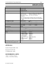
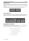
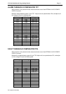
CURRENT CONSUMPTION
Zones Fitted Quiescent Current Quiescent + 2 AZF'S in alarm +1A of Bell +1 Amp ACF
8 150 mA 2.23 AMPS
16 250 mA 2.33 AMPS
24 350 mA 2.43 AMPS
32 450 mA 2.53 AMPS
40 550 mA 2.63 AMPS
48 650 mA 2.73 AMPS
56 750 mA 2.83 AMPS
64 850 mA 2.93 AMPS
Note:
1: Each installation would require individual battery calculations to be performed for load capacity and
power supply capacity.
2: Each IFS-717 relay board, can add 370 mA (in alarm and quiescent) current per board.