


IFS-2600 Installation & Programming Manual Page 61
P/N 10069 ECN08-0066
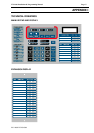
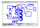
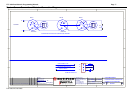
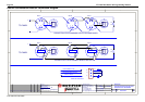
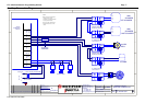
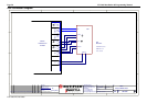
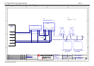
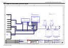
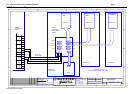
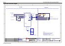
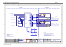
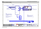
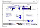
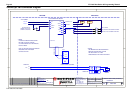
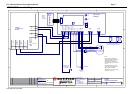
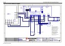
MIMIC Connection Diagram
1
1
2
2
3
3
4
4
D D
C C
B B
A A
Rev
Size
Drg.
No.
Title
Sheet:
Drawn/
Traced
Engineer
Design
Approved
This Drawing mustnot be used for Construction
unlesssigned as approved
7 Columbia Court,
Norwest Business Park
BaulkhamHills NSW 2153
AUSTRALIA
Tel
Fax
Email: support@inertia.com.au
A4
No.
Revision- revise on CAD. Do not amend byhand Eng. App. Date
Copyright
This document is&shall
remain thepropertyof
NotifierInertia FireSystems
Unauthoriseduse of this
documentin anyway is
prohibited.
Drawing File No.
C
O
61 2 9894 1444
61 2 9899 4156
=DocumentFullPathAndName
Of:
A
1 1
2/2/04 G.W.
ZONES 1-8 ZONES 9-16
PCB810
PCB811
PCB812 PCB812
PCB812
ZONES 17-24
SERIALBUS
MIM/26/KIT
MIM/EXT/26 MIM/EXT/26
MIM/26/KIT
1-8
9-16
17-24
25-32
33-40
41-48
49-56
57-64
Max 120 Meters
26-MIM-CON
N/O
BELL
0V
+24
TP 0V
ACF
0V
+24
HOLD
0V
+24
AUX
MAFISO
DOOR
DATA
CLK
DOOR
INPUT
WARN
0V
+24
MIMIC
+
-
HOLD
DATA
CLK
+24
0V
FOR 8 ZONES
FOR EXTRA ZONES
STANDARD SIZES 8, 24 AND 64 ZONES
4/0.75mmcable
POWER AND SIGNAL RETURN
FITTED WITH
IFS2600 MIMIC
DRIVER
IFS2600
TERMINATION
BOARD