


Page 56 IFS-2600 Installation & Programming Manual
P/N 10069 ECN08-0066
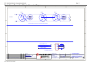
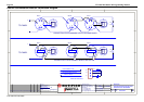
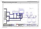
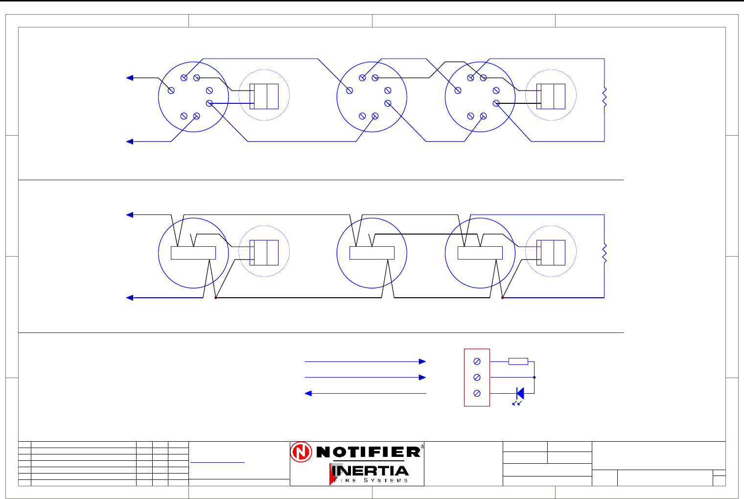
Hochiki Conventional Detector Connection Diagram
1
1
2
2
3
3
4
4
D D
C C
B B
A A
Rev
Size
Drg.
No.
Title
Sheet:
Drawn/
Traced
Engineer
Design
Approved
This Drawingmustnot be usedfor Construction
unlesssigned as approved
7 Columbia Court,
Norwest Business Park
BaulkhamHills NSW 2153
AUSTRALIA
Tel
Fax
Email: support@inertia.com.au
A4
No.
Revision -revise on CAD. Do not amend byhand Eng. App. Date
Copyright
This document is &shall
remain the property of
NotifierInertia Fire Systems
Unauthorised useof this
documentin anyway is
prohibited.
Drawing FileNo.
C
O
61 29894 1444
61 29899 4156
=DocumentFullPathAndName
Of:
+
-
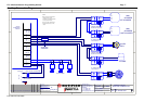
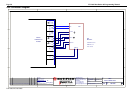
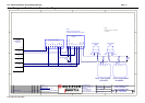
TO PANEL
1
2
3
4
5
67
DET A
-D
+D
+R
RIP
1
2
3
4
5
67
DET B
-D
+D
+R
RIP
EOL
4K7
1
2
3
4
5
67
DET C
+
-
TO PANEL
CONNECTION FOR DFG-60BLKJ SEALED DETECTOR
DET A
-D
+D
+R
RIP
-D
+D
+R
RIP
EOL
4K7
L CS
DET B
L CS
DET C
L CS
RED
BLUE
WHITE
CONNECTION FOR STANDARD DETECTORS AND BASES
+R
+D
-D
470R
+R
+D
-D
Not current limited (3-24 V)
Current limited 10 mA
Common Return
REMOTE INDICATOR
HOC-DET
A
HOCHIKI
CONVENTIONAL DETECTOR
CONNECTION DIAGRAM
1 1
I PERRY I PERRY
I PERRY