


Page 44 IFS-2600 Installation & Programming Manual
P/N 10069 ECN08-0066
APPENDIX G
SUMMARY OF TERMINATIONS AND CAUTIONS
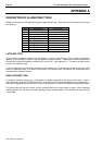
MCP LOOP
Used for the looping of the manual call point to a particular zone chosen for indication. This is achieved by
wiring from the zone, to the MCP, to the MCP loop then out to the field with the EOL across the last detector.
The MCP is the first device on the circuit and both fault and alarm conditions will be indicated.
DETECTION ZONES
Refer to list of compatible actuation devices for detectors which may be used. Any other hard contact device
may be used on these detection zones. An end of line resistor (E.O.L) of 4K7 ohms is required.
RELAY OUTPUTS
Relay outputs are voltage free change over contacts rated at 24VDC 1Amp (resistive). DO NOT attempt to
switch 240VAC with these relay contacts.
Note: Relay Contacts Shown At Terminals (NC, C, NO) Are For The Relay In a De-energised State.
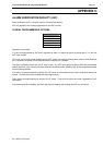
BELL OUTPUTS
This output is fused at 1 Amp and can drive up to 10 NIFS bells as specified. Output is also monitored and if
no bells are connected an EOL resistor (4K7 ohms) is required across the output terminals.
ACF OUTPUTS
This output is fused at 1 Amp. Output is also monitored and if no ancillary devices are connected, an EOL
resistor (4K7 ohms) is required across the output terminals.
WARNING SYSTEM
Connection for warning systems such as Occupant Warning System or electronic sounders.
DOOR HOLDER OUTPUTS
When a door holder transformer is fitted to the panel, this output becomes functional. Output is rated at 3
Amps maximum and can power up to 30 NIFS style door holders continuously. (Nom. 80mA each). Output is
separately fused at 3A (FS-1). Jumper JP3 if fitted will disable this output, i.e. 24V DC output all the time. The
Door Holder Output can be isolated using the ACF Isolate function.
AUXILIARY POWER & MIMIC POWER
A total auxiliary power draw of 500mA is available from the auxiliary power and mimic power terminals. This
output is fused at 1 Amp (FS-3) and is battery backed.
MAF ISOL & TRANSPONDER 0V
A 0V signal is switched back from the transponder test switch and is used for indication purposes at the FIP.
This will indicate as MAF ISOLATED and initiate a common fault. It can also used for an external device to
indicate a fault.
MIMIC DATA & CLOCK
These outputs together with the mimic power terminals are used to serially communicate with the mimic
panels when fitted. EOL resistor is not required on these lines.
NOTE: Firmware must be Version 6 or above for mimic operation
AC INPUT
Mains step down transformer output (30VAC) is connected at these terminals. DO NOT connect 240VAC to
these terminals.