


IFS-2600 Installation & Programming Manual Page 15
P/N 10069 ECN08-0066
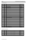
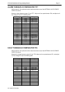
ALARM THRESHOLD COMPARATOR TP7
With the panel in the quiescent mode, measure and take note of the INTERNAL 24V DC POWER
SUPPLY as above.
Measure voltage between system 0V and TP7. Adjust multi-turn potentiometer VR4, and adjust until
the voltage is as per the following table.
Rail Voltage 3.3V Setting Range
20.6 2.833 2.80 to 2.86
21.0 2.888 2.86 to 2.92
21.5 2.956 2.93 to 2.99
22.0 3.025 2.99 to 3.06
22.5 3.094 3.06 to 3.12
23.0 3.163 3.13 to 3.19
23.5 3.231 3.20 to 3.26
24.0 3.300 3.27 to 3.33
24.5 3.369 3.34 to 3.40
25.0 3.438 3.40 to 3.47
25.5 3.506 3.47 to 3.54
26.0 3.575 3.54 to 3.61
26.5 3.644 3.61 to 3.68
27.0 3.713 3.68 to 3.75
27.5 3.781 3.74 to 3.82
27.6 3.795 3.76 to 3.83
28.0 3.850 3.81 to 3.89
FAULT THRESHOLD COMPARATOR TP6
With the panel in the quiescent mode, measure and take note of the INTERNAL 24V DC POWER
SUPPLY as above.
Measure the voltage between system 0V and TP6. Adjust multi-turn potentiometer VR1, and adjust
until the voltage is as per the following table.
Rail Voltage 0.6V Setting Range
20.6 0.600 0.59 to 0.61
21.0 0.612 0.61 to 0.62
21.5 0.626 0.62 to 0.63
22.0 0.641 0.63 to 0.65
22.5 0.655 0.65 to 0.66
23.0 0.670 0.66 to 0.68
23.5 0.684 0.68 to 0.69
24.0 0.699 0.69 to 0.71
24.5 0.714 0.71 to 0.72
25.0 0.728 0.72 to 0.74
25.5 0.743 0.74 to 0.75
26.0 0.757 0.75 to 0.76
26.5 0.772 0.76 to 0.78
27.0 0.786 0.78 to 0.79
27.5 0.801 0.79 to 0.81
27.6 0.804 0.80 to 0.81
28.0 0.816 0.81 to 0.82