


Page 14 IFS-2600 Installation & Programming Manual
P/N 10069 ECN08-0066
ALIGNMENT AND ADJUSTMENT
PCB2006 POWER SUPPLY BOARD
INTERNAL 24VDC (nom) POWER SUPPLY
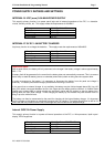
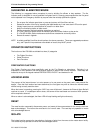
With batteries disconnected and no alarms present, measure voltage across the 0V and MAIN test
points on the 2006 power supply board and, if necessary, adjust the multi-turn potentiometer VR2 until
voltage is 26.5V 0.05V (26.45V – 26.55V).
Current limiting is fixed and field adjustment is not possible.
INTERNAL 27.3 VDC BATTERY CHARGER
With batteries disconnected and no alarms present, measure voltage across the 0V and CHARG test
points on the 2006 power supply board and, if necessary, adjust the multi-turn potentiometer VR1 until
voltage is 27.3V 0.05V (27.25V – 27.35V).
Current limiting is factory preset and field adjustment is not required.
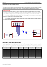
EXTERNAL 24VDC (nom) POWER SUPPLY (if fitted)
With batteries disconnected and no alarms present, measure voltage across Remote Input terminals
on PCB2005 and adjust the voltage on the external power supply until the voltage is 26.5V 0.5V
(26.0V – 27.0V). Note: This voltage is not critical for the operation of the IFS-2600 panel, but the
voltage must not go outside the limits as specified for the field ancillaries that it powers.
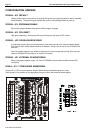
PCB2005 TERMINATION BOARD
INTERNAL 5VDC POWER SUPPLY TP8
All parameters are fixed and field adjustment is not possible.
POWER SUPPLY COMPARATOR REFERENCE VOLTAGE TP10
With the panel in the quiescent mode, measure voltage between system 0V and TP10. Adjust multi-
turn potentiometer VR3 until voltage is 7.0V 1% (6.93V – 7.07V)
NON ADJUSTABLE TEST POINTS
TP8 = 5.0 VDC 5% 5VDC POWER SUPPLY
TP5 = 12.0 VDC 5% 12VDC POWER SUPPLY
(If these test point voltages are not correct, please return the main termination board to the factory for
repair.)