


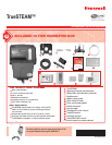

TrueSTEAM Humidification System
7 69-2285EFS—03
M27733
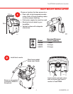
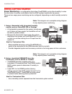
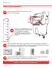
Loosen captive cover screw.
Slide cover out from front.
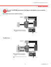
WiththeTrueSTEAMcoverremoved,youwillseesixDIP
switches to the left of the interface panel. This manual refers to
DIPs1-6fromlefttoright.DIP3,4and5offerdifferentwiring
configurations for how to humidify. (DIPs 1-2 are associated with
maintenance. Details for DIPs 1-2 are found in the maintenance
section.) DIP 6 is not used at this time.
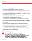
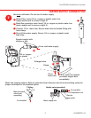
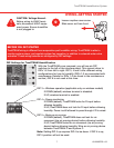
CAUTION: Voltage Hazard.
Before wiring to HVAC termi-
nals,disconnectHVACequip-
ment power. Ensure humidifier
is not plugged in.
DIP Settings for TrueSTEAM Humidification
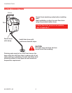
WIRING–GETTING STARTEDDRAIN CONNECTION
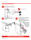
BEFORE YOU GET STARTED
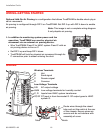
TrueSTEAM wiring is different from evaporative pad humidifier wiring. TrueSTEAM is able to
monitorsystempower,andregulatesystemfanoperation,inadditiontosolenoidwatervalve
actuation. These wiring features are configured by DIP settings.
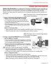
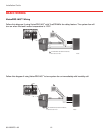
DIP 3 = Wireless operation (applicable only on wireless models)
If DOWN (default) wireless terminal is disabled.
IfUP,wirelessterminalisenabled.
DIP 4 = Power monitoring.
IfDOWN(default),TrueSTEAMlooksforRinputbefore
allowing humidity.
IfUP,TrueSTEAMdoesnotlookforRinputbeforeallowing
humidity. Power is still allowed to pass through if R is wired.
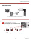
DIP 5 = Back-up air proving.
IfDOWN(default),TrueSTEAMdoesnotlookforair
movement (via air proving device) before allowing humidity.
IfUP,TrueSTEAM looks for air movement (via air proving
device) before allowing humidity. Wire an air proving device
between TrueSTEAM C and System C.
Note:SettingDIP5uprequiresDIP4tobedown.IfDIP4isup,
DIP 5 position will not be used.
M28683